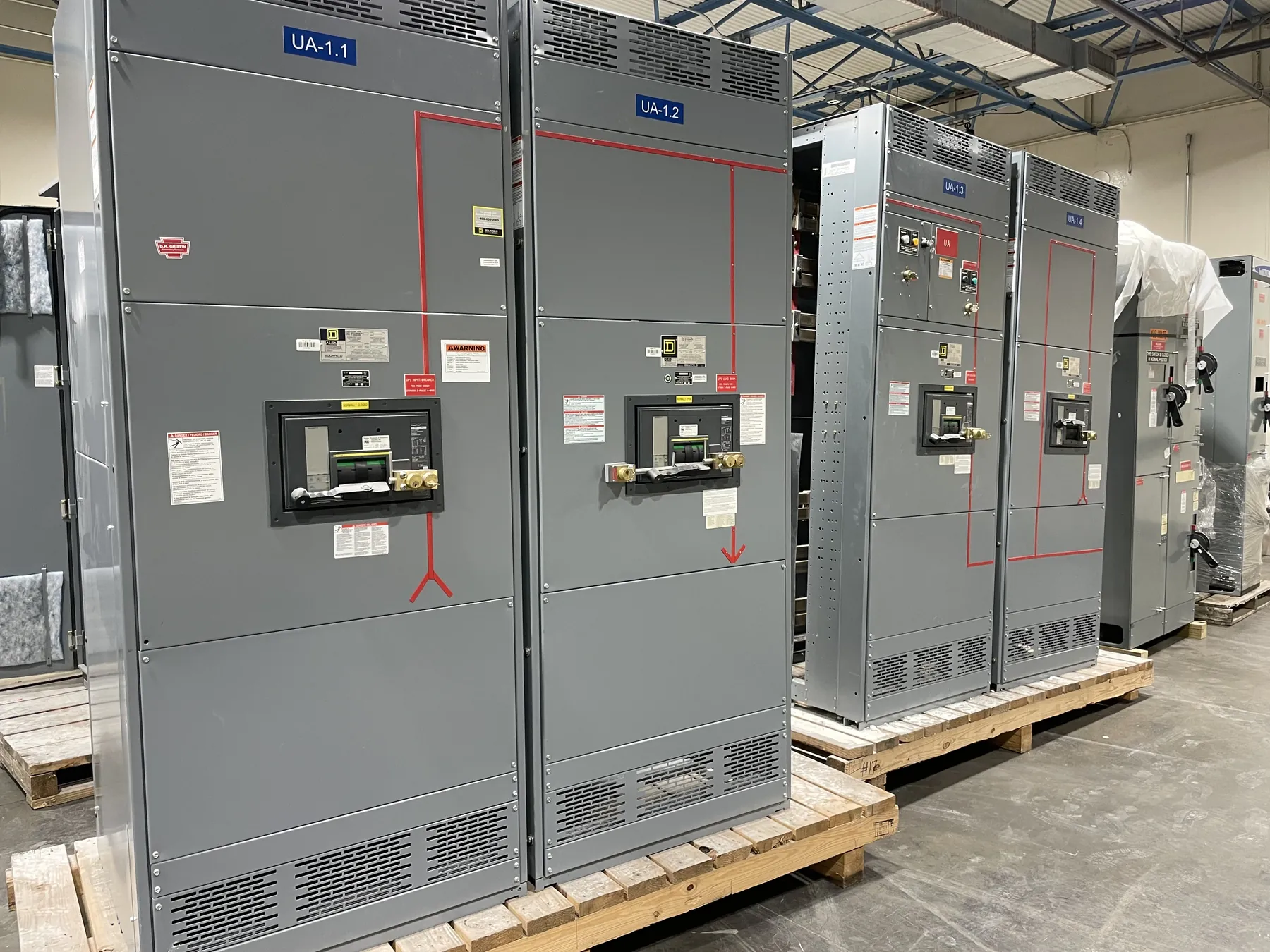
Industrial Switchgear for Fallon, Nevada Facilities
Industrial electrical distribution in Fallon starts with the facility’s actual process loads, operating patterns and service conditions—not a generic equipment schedule. A manufacturing line, water-handling process, agricultural operation or other industrial installation may combine steady loads with motors that start frequently, drives that vary speed and equipment that cannot tolerate an unplanned interruption. Those differences affect switchboard or switchgear configuration, protective-device selection, feeder arrangement and the information needed for a sound quotation. Custom equipment can be manufactured in the United States with all-American components and shipped to Nevada; project design and ratings still require review against the specific site and electrical system.
Build the Design Around Load Profiles and Motor Starts
For a Fallon project, begin by documenting connected loads and how they operate over time. Identify which motors run continuously, which cycle or start together, and whether process sequencing limits simultaneous demand. Motor nameplate and application data, starting frequency, acceleration requirements and the driven load all help engineers evaluate starting conditions. A motor that starts against a heavy load can create a different electrical demand from one that starts unloaded, even when their nominal power ratings appear similar.
Starting method is another design input. Across-the-line starting, reduced-voltage methods and variable-frequency drives have different effects on the supply, controls and protection scheme. The right choice depends on the motor, process, upstream source and operating objectives; it should not be selected from a switchgear quotation alone. Provide the intended starting method and any process constraints, such as required acceleration behavior or limits on voltage disturbance, for engineering review.
Integrate Variable-Frequency Drives with Distribution
Variable-frequency drives can support process control and adjustable motor speed, but they introduce application details that should be coordinated with the distribution equipment. Identify each drive’s input requirements, associated motor, bypass arrangement if applicable, and expected operating modes. Clarify whether a drive is furnished within the equipment lineup or supplied separately, since that affects physical space, electrical interfaces, controls and responsibility boundaries.
Drive-related harmonic effects, cooling needs, cable arrangements and protective-device coordination may matter to the overall installation. These questions depend on the drive and system design; they should be reviewed by qualified electrical engineers rather than assumed from a general product description. The quotation package should distinguish switchgear functions from drive functions and identify which party provides each component, connection and control interface.
Evaluate Duty, Available Fault Current and Ratings
Equipment selection must account for the electrical system at the point of connection, including the available fault current and the protective-device interrupting and withstand capabilities required for the application. The equipment’s ratings are not interchangeable with the system’s nominal voltage, and a rating stated for one component does not establish that every assembly or connected device is suitable. Confirm the system voltage, grounding arrangement, source information and applicable fault-current data with the project’s electrical designer or serving utility as appropriate.
Load duty also shapes the design. Continuous operation, repeated starts, process changes and planned expansion can influence feeder sizing, device selection and provision for future circuits. These decisions need load calculations, equipment data and site-specific engineering review. Applicable standards and any requested product listing must be confirmed for the particular equipment type and configuration; UL 891 applies to applicable low-voltage switchboards, not to every form of switchgear or every voltage class.
Set a Protective-Device Coordination Objective
Coordination is more than choosing breaker sizes. The project team should state what it wants the protection scheme to accomplish—for example, limiting an interruption to the affected motor or feeder where practical, while retaining the protection required for equipment and conductors. That objective must be evaluated against the system’s fault-current range, device characteristics, motor-starting behavior and upstream protection. Selective coordination cannot be presumed simply because devices are arranged in sequence.
Provide the available upstream device information, downstream loads and any existing coordination study or design criteria. A qualified engineer can assess time-current relationships, motor protection and system constraints, then identify whether proposed devices support the project objective. Changes to the source, transformer, feeder length or protective devices can affect results, so final coordination depends on verified project data rather than a product description.
Prepare a Fallon Project Quotation Package
Useful quotation inputs include one-line diagrams, load schedules, motor and drive data, system voltage and grounding details, available fault-current information, upstream protection, preferred lineup arrangement, enclosure conditions and required interfaces. Note environmental conditions at the installation location, including expected temperature, dust, moisture and indoor or outdoor exposure, as well as access limits that may affect equipment dimensions or placement. Fallon-area logistics and facility access can influence shipment planning, but no delivery date should be assumed before the configuration and schedule are confirmed.
Also identify required documentation, controls, metering, spare provisions and expansion needs. A complete review helps separate confirmed requirements from open engineering questions before manufacturing. New custom industrial distribution equipment can be built in the United States using all-American components and shipped nationwide, including to Nevada. Final ratings, listings, coordination, interfaces and project suitability remain subject to qualified engineering review and confirmation of the site conditions.