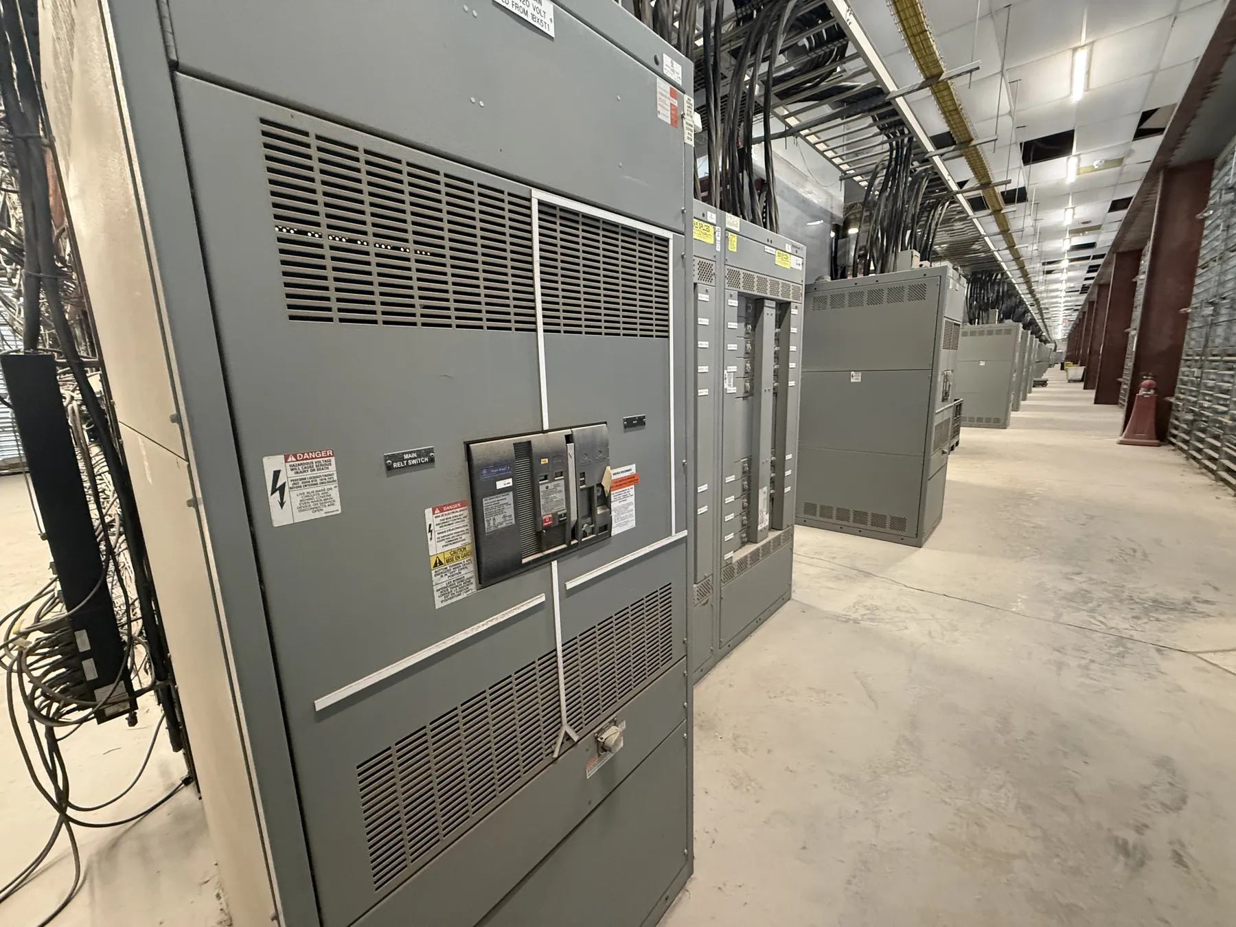
Metal-Enclosed Switchgear for Fallon Project Requirements
For a Fallon facility, metal-enclosed switchgear should be selected around the electrical system it will serve—not by enclosure name alone. Start with the one-line diagram, system voltage, available fault current, connected loads and the role of the assembly in the distribution system. A site may have a utility service, on-site generation, transformers, large motors or multiple feeder groups; each can affect the equipment arrangement and protective-device decisions. Project conditions such as indoor or outdoor placement, dust, temperature exposure, access routes and available installation space also influence the enclosure and layout. These details need review by qualified electrical professionals before equipment ratings or construction are finalized.
Switch, Fuse and Breaker Configurations — Metal-Enclosed Switchgear in Fallon, NV
A metal-enclosed assembly can be configured with switches, fuses, circuit breakers or combinations suited to the intended function. A switch-and-fuse arrangement may offer a compact way to provide switching and overcurrent protection for a defined circuit, while breaker-based designs can provide a different operating and coordination approach. The right choice depends on the load, fault duty, protection objectives, maintenance strategy and system design. Neither arrangement is automatically preferable for every application.
For quotation, identify which circuits require switching, which require protective devices, and whether the equipment serves incoming service, transformer, motor or feeder functions. Include the intended device types and ratings if established by the project engineer. If they are not established, provide the available design information so the engineering review can identify open decisions rather than assume them.
How Metal-Enclosed Differs from Metal-Clad
Metal-enclosed and metal-clad describe different construction approaches; the terms should not be treated as interchangeable. Metal-clad switchgear generally uses compartmentalized construction with specified separations and removable circuit-interrupting devices, while metal-enclosed equipment describes a broader category of enclosed assemblies. A metal-enclosed design may use fixed or otherwise arranged components, depending on its application and construction. The product description alone does not establish the internal barriers, service access, device removability or applicable standard.
When comparing proposals, ask for the equipment arrangement, compartment boundaries, access provisions and intended maintenance access. Confirm that the stated construction matches the project specification. UL 891 applies to applicable low-voltage switchboards; it should not be taken as a blanket standard or listing claim for all metal-enclosed switchgear. Applicable standards and any product listing must be confirmed for the actual equipment and voltage class.
Barriers, Fault Duty and Grounding — Metal-Enclosed Switchgear in Fallon, NV
Internal barriers can help separate components or limit access between sections, but their presence and function depend on the design. Specify which components need separation and what access constraints the installation requires. The available fault current at the equipment location is essential to evaluating interrupting and withstand requirements. Fault-duty ratings are not the same as system voltage: both must be established and checked against the project’s electrical conditions and equipment configuration.
Grounding is another project-specific design element. The grounding method, connections to the facility grounding system, and treatment of neutral conductors must align with the one-line diagram and applicable requirements. Provide the design basis and site information for review; do not infer grounding details from a general product description. Qualified engineers must confirm the complete design, ratings and coordination for the installation.
Fallon Load Profiles and Protective Coordination
Describe the load profile by identifying major load types, operating patterns and expected changes. Motor loads deserve particular attention: motor starting requirements, starting method and the impact of starting current on upstream and downstream protection can shape device selection. Provide motor data and relevant control details when available. Also identify loads that should remain supplied when another circuit trips, and any operational priority among feeders.
Protective-device coordination is not simply a matter of selecting a breaker or fuse size. The project should state its coordination objective, such as the desired relationship between upstream and downstream protective devices, and provide the system information needed to evaluate it. Available fault current, transformer data, conductor details and device characteristics may all matter. A qualified engineer must assess whether the chosen protection scheme meets the project’s requirements.
Quotation Information, Site Interfaces and Delivery
A useful quotation package includes the one-line diagram, system voltage, available fault-current information, load schedule, motor data, required device arrangement, grounding details, enclosure location and applicable project specifications. Include interfaces such as incoming and outgoing cable entry, conduit or bus connections, control wiring, metering and space limitations. State any site access or installation constraints that could affect shipping dimensions or handling. For a Fallon site, these logistics should be reviewed with the project team; no particular site conditions or delivery schedule should be assumed.
We manufacture new custom switchgear and power-distribution equipment in the United States using all-American components, with short lead times as a manufacturing objective and shipping available nationwide, including to Fallon. Final scope, ratings, listings, interfaces and schedule require confirmation against the project documents and engineering review. Clear inputs help align the proposed metal-enclosed configuration with the facility’s actual loads and operating needs.