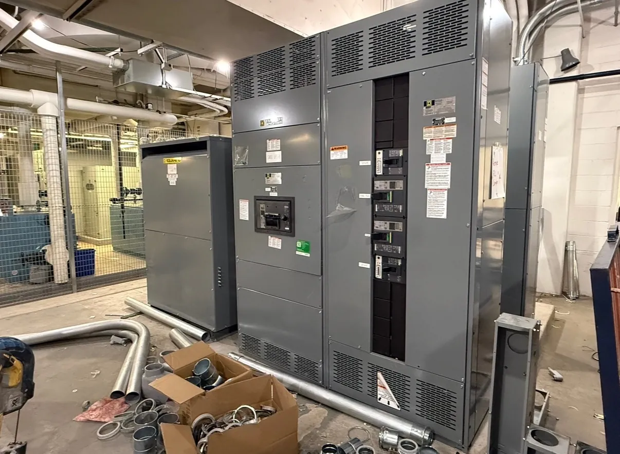
Hospital Switchgear Planning for Fallon, Nevada
Hospital electrical distribution must support the facility’s clinical functions, emergency-power strategy and planned expansion—not just the connected load shown on an early one-line diagram. For a Fallon project, the design team should establish which services are supplied from normal power, which transfer to emergency power, and how those systems connect to switchboards, transfer equipment, generators and downstream panels. A custom equipment package can be developed around the project documents and confirmed requirements; the equipment manufacturer does not replace the engineer responsible for the facility’s electrical design.
Fallon’s location also makes practical coordination important. The project team should confirm delivery access, receiving arrangements, equipment-room dimensions, door and corridor clearances, environmental conditions and construction sequencing before equipment is released for manufacture. These details affect shipping configuration and installation planning, but do not establish an assumed delivery date or a local manufacturing presence.
Essential Electrical System Branches and Their Interfaces
Hospital essential electrical systems are organized around the functions that must remain available when normal power is interrupted. Depending on the facility’s classification, design and applicable requirements, the system may include life safety, critical and equipment branches. The exact branch arrangement, loads assigned to each branch and permitted connections must be determined by the project’s qualified electrical and healthcare design professionals, not inferred from a generic switchgear layout.
For equipment planning, the one-line should show how each branch is fed and where transfer occurs. Designers should identify whether transfer switches are separate devices or part of an integrated assembly, how emergency and normal sources reach them, and which downstream distribution sections serve each branch. Clear separation and labeling can aid installation, inspection and future maintenance, while the physical arrangement must still meet the applicable design, listing and code requirements. The switchgear quotation should identify interfaces and boundaries so that responsibility for transfer equipment, feeders, controls and downstream distribution is clear.
Source Transfer, NFPA 99 and NFPA 110
NFPA 99 addresses health care facility systems and requirements that depend on the facility and its risk classification. NFPA 110 addresses emergency and standby power systems, including emergency power supply systems and related transfer equipment. Their applicability and specific provisions must be evaluated against the project’s adopted codes, facility conditions and authority having jurisdiction. A reference to either standard on a design document does not, by itself, establish that every switchboard or component is covered by that standard.
Transfer design requires decisions about source arrangement, the loads assigned to each transfer device, control interfaces and the intended response to source conditions. The engineer should define whether loads transfer together or in staged groups and how generator capacity and load sequencing are considered. Transfer equipment has its own ratings and listing considerations. For low-voltage switchboards, UL 891 may apply where appropriate; it should not be treated as a blanket standard for all switchgear or transfer equipment. Product ratings, listings and configuration must be confirmed for the actual assembly and application.
Load Profiles, Motor Starting and Equipment Ratings
A useful Fallon hospital equipment schedule distinguishes continuous demand from intermittent and starting loads. Include major motors such as pumps, air-handling equipment, compressors and other mechanical loads, along with their starting method and expected operating sequence. Motor starting can affect voltage dip, generator response, transfer strategy and protective-device selection. The design team should assess those interactions rather than rely only on motor nameplate data or an aggregate load total.
Quotation inputs should include the one-line diagram, load schedules, available fault-current information, system grounding, operating voltage and frequency, required equipment ratings, enclosure and room conditions, and specified control or metering features. A voltage rating is not the same as the system’s nominal voltage, and interrupting, withstand and other ratings must be selected for the application. Any unclear or missing information should be identified for engineering review rather than filled in by assumption.
Protective-Device Coordination and Commissioning
The coordination objective should be stated by the project engineer: for example, which protective devices should operate for specified fault conditions, and where selectivity is required or desired. Complete, compatible device data and the system study are essential to evaluate that objective. The analysis may need to consider normal and emergency source conditions, generator characteristics, transfer configurations and changes in available fault current. Coordination cannot be guaranteed from switchgear selection alone; device settings and system performance depend on the approved design and site-specific study.
Commissioning responsibilities should be assigned across the electrical engineer, equipment suppliers, installing contractor, generator and transfer-equipment providers, testing personnel, facility representatives and other parties named in the project documents. The commissioning plan should define submittal reviews, factory documentation, field inspections and functional testing of the complete power system, including source transfer and relevant branch interfaces. Acceptance criteria, test methods and records should follow the contract documents and applicable requirements. Equipment manufacture is one part of that process, not a substitute for site commissioning.
Custom Equipment Scope for a Fallon Hospital Project
For a new manufactured package, the team should resolve equipment boundaries, incoming and outgoing feeder details, bus arrangement, metering, controls, spare provisions and future expansion needs before final approval. Room layout, cable entry, heat dissipation, access for installation and the relationship to adjacent equipment also affect the practical design. Changes to load assignments or source arrangements after submittal can affect engineering and manufacturing scope, so early coordination is valuable.
Our U.S.-built assemblies use all-American components, support short lead times and can ship nationwide, including to Nevada. Actual schedule, configuration and applicable ratings depend on the approved project requirements and must be confirmed during quotation and engineering review. Providing coordinated drawings and complete electrical data helps establish a clear, buildable scope for the hospital’s distribution system.