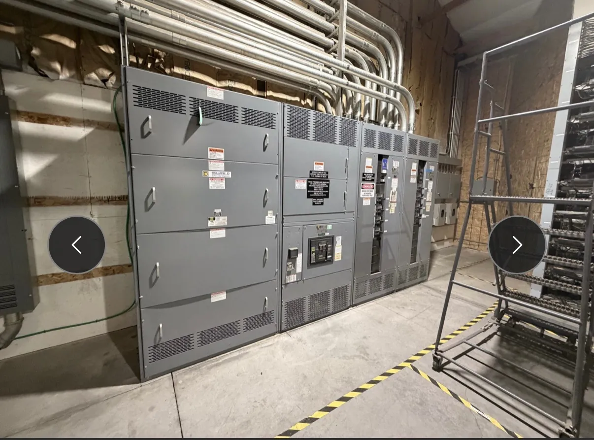
Medium-Voltage Switchgear for Fallon, Nevada Projects
Medium-voltage switchgear brings together switching, protection and connections for circuits operating above the low-voltage range. For a Fallon facility, selecting it starts with the electrical system—not a catalog label. The project team must establish the nominal system voltage, grounding arrangement and operating conditions, then determine how the equipment will connect to the utility or upstream source and to downstream transformers, motors or other loads. Those details shape the equipment configuration and its ratings.
Equipment can be manufactured to project requirements for customers in Fallon and shipped nationwide from a U.S. manufacturer. Assemblies use all-American components and are built in the USA. Short lead times may be supported, but schedule depends on the approved design, component requirements and project conditions; it should be confirmed for each quotation.
Define Voltage Class, Fault Duty and Insulation Level — Medium-Voltage Switchgear in Fallon, NV
Voltage class identifies the range of system voltage for which the switchgear is designed. It is not interchangeable with a current rating, and it should not be inferred from a facility’s service description alone. Confirm the nominal and maximum system voltage, frequency, grounding method, and any relevant source or transformer information with the project’s electrical engineer and serving utility, as applicable.
Available fault current at the proposed connection point is essential to equipment selection. The engineer must determine the expected fault duty and verify that the selected assembly and protective devices are suitable for it. Insulation level is a separate design consideration: it addresses the equipment’s ability to withstand specified electrical stresses. It is selected in relation to the voltage class and system conditions, not as a substitute for fault-duty review. Final ratings and configuration require project-specific engineering confirmation.
Match the Lineup to Fallon Load Profiles
A useful load schedule distinguishes continuous demand from changing or intermittent loads. Identify major motors, transformer loads, process equipment, seasonal operation, planned expansion and any loads that can start or operate together. For motor applications, starting method and starting current affect voltage behavior, protective-device settings and the coordination of upstream and downstream equipment. Large or frequent starts may make the relationship between motor protection and feeder protection especially important.
Load information also guides the number and purpose of lineup sections, feeder arrangements, metering provisions and future connection points. A design that accounts for likely operating patterns can avoid treating every load as identical. Where operating data is incomplete, clearly label assumptions in the design package so the engineer can review their effect before equipment details are finalized.
Choose Protection and Coordination Objectives
Protective relays detect defined electrical conditions and initiate a trip through the associated switching device. Relay functions and settings depend on the circuit, connected equipment, available fault current and the intended protection strategy. The project should state what the protection system is meant to accomplish—for example, limiting an affected circuit while maintaining service to other loads where the system design permits.
Coordination is not established by selecting relays in isolation. A qualified engineer reviews device characteristics and settings across the relevant system, including upstream protection, transformers, motor circuits and downstream devices. The review must use accurate source and equipment data, and it may need to consider changes in source configuration or operating mode. No particular coordination outcome can be assumed before that study and site review are complete.
Plan Cable Terminations and Equipment Interfaces
Cable termination design depends on the specified cable type and size, conductor material, number of cables per phase, routing direction and available bending and access space. Confirm whether incoming and outgoing connections enter from above or below, and provide the cable manufacturer and termination information needed for the selected arrangement. Interface details also include grounding provisions, control wiring, auxiliary power, metering and communication requirements where applicable.
Fallon site conditions should be documented rather than presumed. The equipment location, indoor or outdoor exposure, room clearances, access route, foundation or support, ambient conditions and cable path can all affect the enclosure and lineup arrangement. Shipping and receiving plans should account for the equipment’s transport configuration and site access. These logistical details are distinct from electrical ratings, but they can determine whether the proposed design is practical to install.
Prepare a Project-Ready Quotation Package — Medium-Voltage Switchgear in Fallon, NV
To support a meaningful quotation, provide the one-line diagram, nominal system voltage and grounding information, available fault-current data, load schedule, motor starting requirements, protection and coordination objective, cable and termination details, and preferred lineup arrangement. Include site conditions, interface requirements, project schedule and any applicable specifications. Identify which documents are preliminary and which have been approved, so open engineering questions remain visible.
Medium-voltage equipment selection and protection design require review by qualified electrical engineers using project data. Ratings, relays, insulation level, terminations and other details must be confirmed for the specific system and installation. UL 891 applies to applicable low-voltage switchboards; it should not be used to characterize medium-voltage switchgear. Final product claims, listings and project requirements should be verified for the exact assembly being specified.