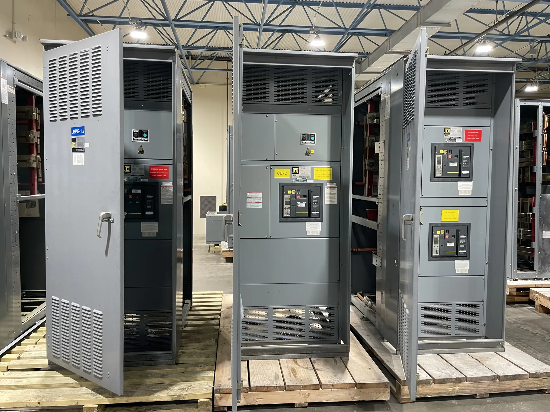
Low-Voltage Switchgear for Fallon, NV Projects
Fallon projects can call for low-voltage switchgear in industrial, agricultural, commercial, municipal, or infrastructure settings, each with a different mix of loads and operating demands. The right lineup depends on more than the nominal system voltage. Engineers need to understand how loads vary over time, which circuits are critical, how motors start, and what maintenance access the facility can provide. A custom design should reflect the actual one-line diagram and site conditions rather than assume that a standard arrangement will fit every application.
We manufacture new custom power-distribution equipment in the United States using all-American components. Assemblies can be configured for a project’s documented requirements and shipped nationwide, including to Nevada. Project scope, ratings, applicable standards, and schedule are confirmed during engineering and quotation; a particular product configuration or compliance status should not be assumed before that review.
Choose a Breaker Arrangement Around the Load
Low-voltage power circuit breaker switchgear may be considered when a project calls for a drawout breaker arrangement and the associated maintenance and operating features. Breaker frame, trip unit, interrupting capability, control power, and compartment configuration all affect the design. A fixed-mounted device may be appropriate for some applications, while drawout equipment can support a different maintenance strategy. Neither choice is universally preferable: selection depends on the owner’s maintenance resources, continuity objectives, available space, and the engineered system.
For Fallon facilities with substantial motor loads, provide motor horsepower or other applicable nameplate information, starting method, expected starting frequency, and any operational sequence that affects simultaneous starts. Large starting currents can influence voltage drop, protective-device settings, and coordination with upstream sources. Variable-frequency drives, soft starters, and across-the-line starters present different electrical characteristics and should be identified early. The engineer can then assess feeder and breaker requirements against the actual load profile.
Compare Maintainability and Physical Access
Maintainability involves more than the ability to remove a breaker. Consider whether equipment will be operated by facility staff or service contractors, the intended maintenance approach, access to the front and rear, room clearances, cable entry, and space for future circuits. Drawout arrangements require suitable room and working access for breaker handling. A compact lineup may reduce footprint but can constrain access or future expansion. The site layout and applicable electrical requirements must be reviewed by qualified professionals before dimensions and access provisions are finalized.
Environmental and building conditions also matter. Share indoor or outdoor placement, ambient conditions, dust or moisture exposure, ventilation constraints, seismic or other project-specific requirements, and transportation access to the installation area. Fallon’s location may affect shipment planning and coordination with the receiving site, but delivery arrangements depend on the finished equipment, route, and project requirements. We do not assume a local facility or project-specific delivery schedule.
Specify Bus Ratings and System Conditions Separately
Bus ratings describe equipment capabilities; they are not the same thing as the system voltage. The project documents should identify the system’s nominal voltage and frequency, available source configuration, and the required bus current rating. Short-circuit and withstand requirements must also be established for the actual installation. These values depend on the electrical system and cannot be selected from a city name or a general product description.
Bus material, arrangement, temperature-rise considerations, neutral configuration, and ground-bar requirements may affect the lineup. The engineer should confirm how the switchgear connects to transformers, generators, utility service, downstream distribution, and any tie breakers. If future capacity is anticipated, identify it as a design objective; spare space alone does not establish that bus or protective devices will support later loads.
Coordinate Protective Devices to the Project Objective
Protective-device coordination starts with a stated objective. A project may seek to limit the extent of an outage, protect equipment, or balance selectivity with other system constraints. The desired result must be evaluated using the source characteristics, conductor data, transformer information, downstream devices, and applicable fault-current information. Breaker trip units and settings cannot be chosen responsibly without this system review.
Provide existing or proposed one-line diagrams, upstream protective-device details, downstream feeder loads, motor data, and available short-circuit or coordination studies when available. If the installation includes multiple sources, transfer equipment, or a tie arrangement, describe normal and alternate operating configurations. Qualified engineers must assess coordination, protection, and arc-flash implications for the complete system. Equipment ratings and project settings require confirmation; they are not established by a quotation request alone.
Discuss UL 1558 and Other Project Requirements
UL 1558 may be relevant to low-voltage metal-enclosed switchgear, depending on the equipment category and project specification. Its applicability should be confirmed for the proposed design; mentioning the standard does not establish that a particular assembly is listed or certified to it. UL 891 applies to applicable low-voltage switchboards and should not be treated as a blanket standard for all switchgear or other equipment. The specification, product scope, and any required listing must be reviewed together.
For a useful quotation, submit the one-line diagram, equipment schedule, system voltage, requested bus and short-circuit ratings, breaker and feeder quantities, motor-starting information, coordination objective, physical layout, and applicable project standards. Include known site and shipment constraints and identify any required interfaces with existing equipment. These details allow the engineering review to clarify assumptions, identify open items, and develop a custom configuration for the Fallon project without presuming unverified ratings, approvals, or lead times.