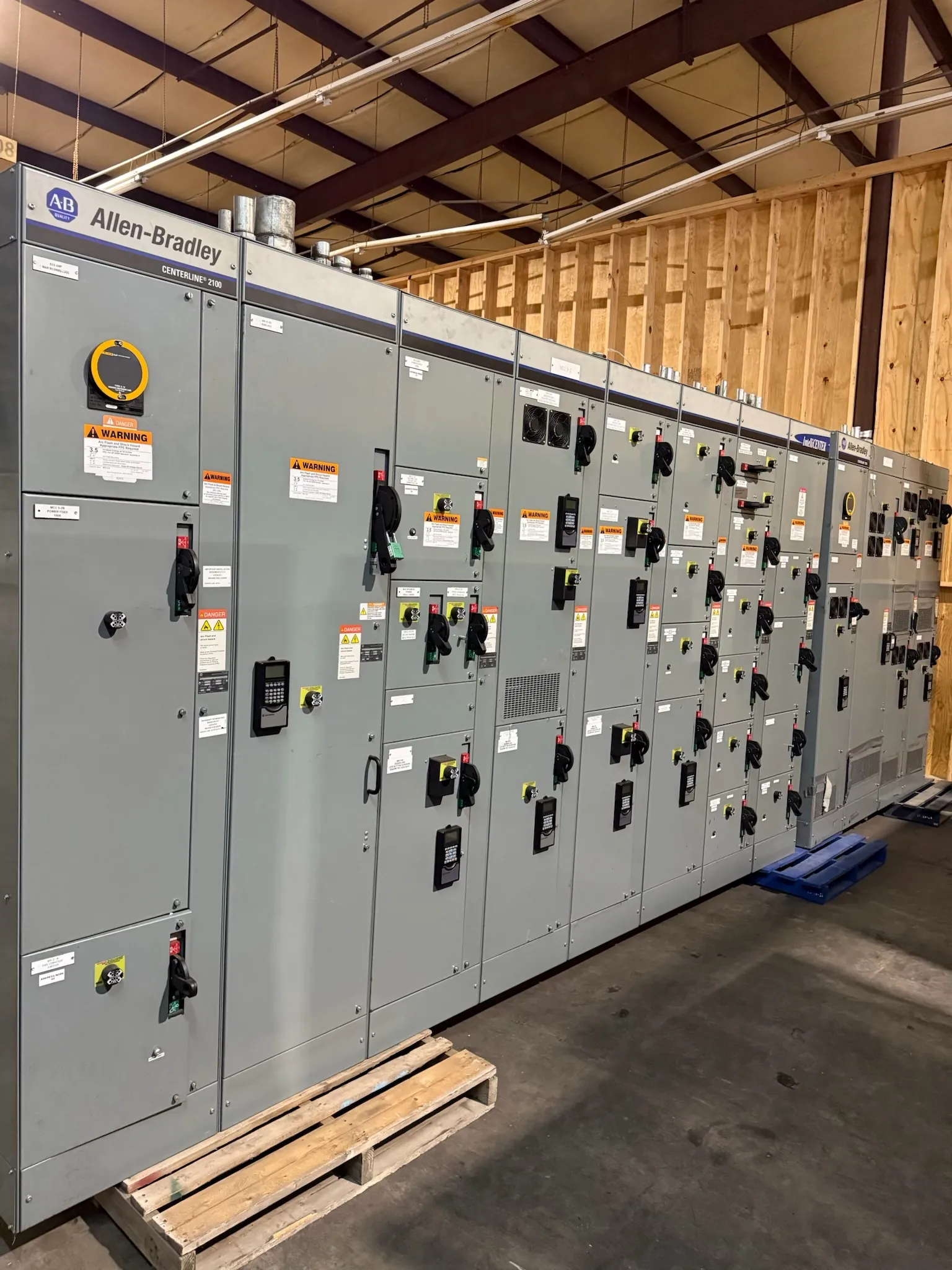
Metal-Clad Switchgear for Fallon, Nevada Projects
Metal-clad switchgear can be a fit for Fallon facilities that need medium-voltage power distribution with separately enclosed components and a coordinated protection scheme. The right lineup depends on the electrical system and the work it must perform—not the city name alone. Start with the one-line diagram, utility or upstream source information, load schedule, and project conditions. These inputs help determine the lineup arrangement, breaker duties, controls, and interfaces before equipment is specified.
Our company manufactures new custom switchgear and power-distribution equipment in the United States, using all-American components, and ships nationwide, including to Nevada. Project-specific design, ratings, applicable listings, and schedule details require review and confirmation. A Fallon delivery also calls for practical coordination around site access, unloading provisions, indoor or outdoor placement, and the receiving facility’s construction sequence. Those details affect shipment planning and installation interfaces, but do not establish an equipment rating or delivery date.
Compartmentalization and Lineup Arrangement
Metal-clad construction separates major functional elements into grounded metal compartments. Depending on the design, these may include the bus, circuit breaker, cable terminations, and control wiring. This arrangement can help contain equipment functions and support defined inspection and maintenance boundaries; it does not eliminate electrical hazards or replace project-specific safety measures.
Compartment layout is a design choice with consequences for footprint, access, cable entry, and future work. The engineer should confirm whether incoming and outgoing cables enter from above or below, where control conduits terminate, and how the lineup connects to transformers, motors, or other switchgear. Room dimensions, door and aisle clearances, ventilation, environmental exposure, and equipment handling routes should be established with the site team. In Fallon, actual indoor conditions, dust exposure, temperature range, and building interfaces should be documented rather than assumed from regional climate.
Withdrawable Breakers and System Interfaces
Withdrawable breakers are designed to move between defined connected, test, and disconnected positions within compatible switchgear. The mechanism, interlocks, shutters, control plugs, and position indication must be coordinated as part of the complete assembly. Confirm the breaker type and ratings against the switchgear design; a breaker’s interrupting rating or continuous-current rating is not the same as system voltage and cannot be selected in isolation.
Useful quotation inputs include the system voltage, frequency, available fault-current information, bus rating, feeder and motor loads, required incoming sources, and the intended arrangement of breakers and compartments. Also identify metering, relaying, control power, communications, and any required interfaces with existing equipment. If the project involves replacement or expansion, provide verified dimensions and interface drawings. Compatibility should be established by qualified engineering review, not inferred from appearance or a general product description.
Grounding, Relaying, and Coordination Objectives
Grounding design ties together the switchgear enclosure, ground bus, cable shields or grounding conductors as applicable, and the facility grounding system. The project engineer should define the grounding method and confirm connections at the source, transformer, lineup, and loads. Ground-fault protection and sensing choices depend on that system configuration and the protection objectives; grounding details should not be guessed from a nominal voltage.
Relay coordination starts with a stated objective, such as isolating a faulted feeder while keeping healthy portions of the system in service where the system design permits. Engineers need source and transformer data, conductor information, motor characteristics, protective-device settings or curves, and available fault-current studies. They assess selectivity, sensitivity, equipment withstand limits, and backup protection together. The desired result must account for both fault clearing and continuity of service; no coordination outcome can be promised without the complete system information and engineering analysis.
Fallon Load Profiles and Motor Starting
For a Fallon project, describe how demand changes over a representative operating cycle: steady loads, scheduled process loads, seasonal variation, standby or emergency sources, and planned expansion. A load list should identify each major motor, its operating duty, starting method, and expected starting frequency. Motor starting can affect voltage at the motor and elsewhere on the system, as well as protective-device selection and relay settings. The project engineer can use these details to evaluate the source, transformer, feeder, and starting arrangement as a connected system.
Clarify whether motors start directly, through reduced-voltage equipment, or with drives, and identify any sequencing or restart constraints. Starting requirements may conflict with sensitive-load continuity or fault-clearing objectives, so those priorities should be stated rather than left implicit. Actual motor data and system studies—not generic assumptions—must guide the final design.
Applicable IEEE C37.20.2 Requirements and Project Review
IEEE C37.20.2 is the applicable standard to evaluate for metal-clad switchgear within its scope. The project specification should identify the required edition and establish which requirements apply to the proposed assembly and its service conditions. Do not assume that citing the standard alone verifies suitability, a particular rating, or compliance of every component and interface. The manufacturer and project engineers should review the specification, design documents, and any required evidence for the specific equipment being quoted.
For a complete request, provide the one-line diagram, load and motor schedules, system and fault-current data, grounding method, relay coordination objective, site and room information, and applicable project specifications. Confirm ratings, standards, listing needs, interfaces, and schedule during technical review. That process gives the Fallon project team a sound basis to evaluate a custom metal-clad lineup for the actual electrical system.