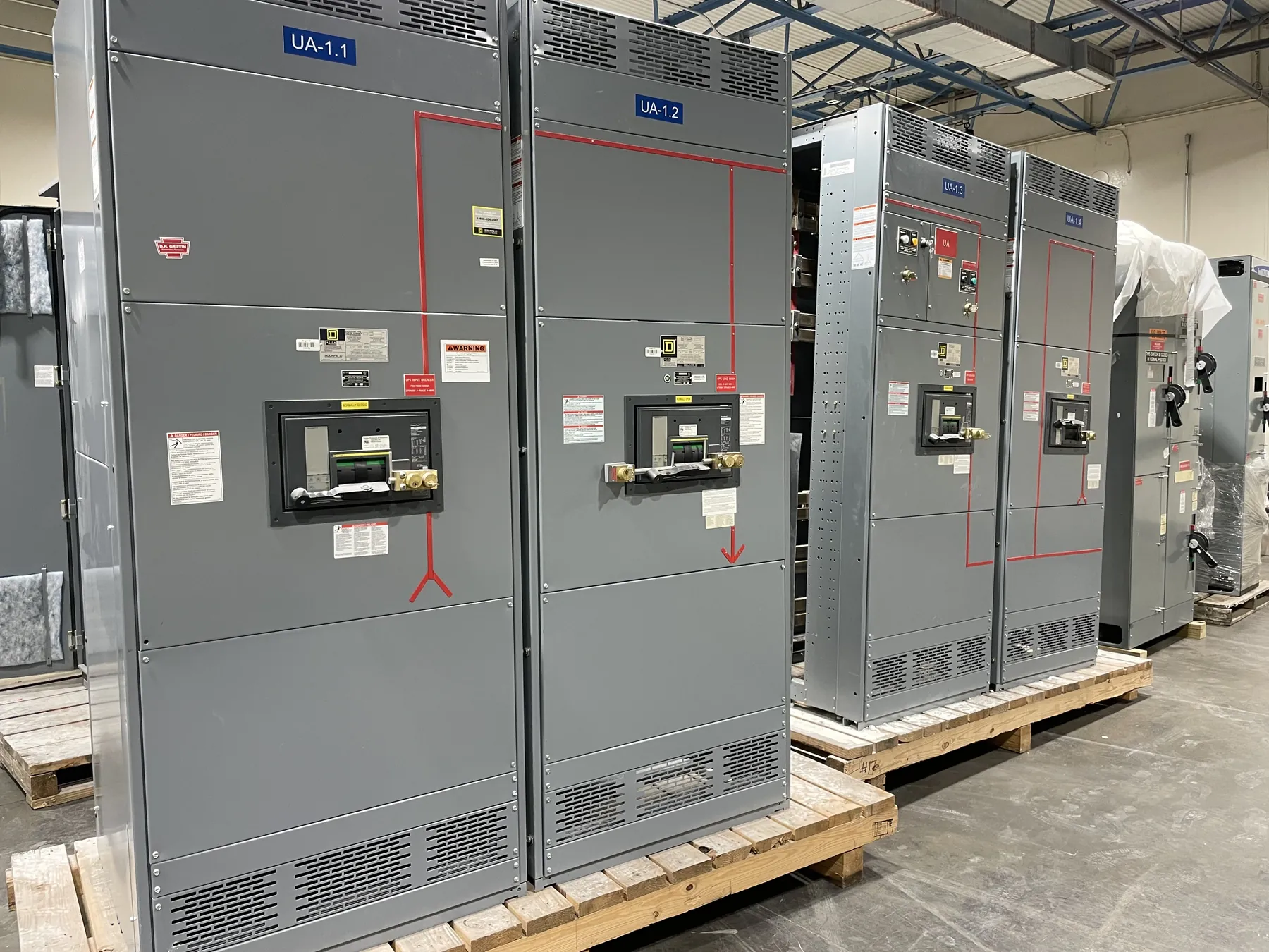
Motor Control Centers for Fallon, Nevada Projects
Fallon facilities that operate pumps, fans, compressors, conveyors, or other motor-driven equipment may benefit from a motor control center (MCC) configured around the actual loads and the way the site runs. A custom MCC can group motor starters, variable frequency drive (VFD) sections, feeder protection, control interfaces, and distribution functions in an organized assembly. The appropriate arrangement depends on the electrical system, operating sequence, environment, and maintenance plan—not simply on the number of motors.
We manufacture new custom power-distribution equipment in the United States using all-American components, and ship nationwide, including to Nevada. For a Fallon project, equipment configuration and shipping arrangements should be reviewed against the site’s access, receiving capabilities, installation schedule, and environmental conditions. No local project conditions should be assumed: facility drawings and site-specific information are needed to develop a suitable design and quotation.
Start With Load Profiles and Motor-Starting Requirements
A useful MCC specification begins with a motor and load schedule. Include each motor’s nameplate information, driven equipment, operating hours or duty pattern, expected starting frequency, and whether it runs continuously, intermittently, or in a sequence with other loads. Identify standby equipment and loads that may start at the same time. These details help engineers evaluate the expected operating profile and avoid selecting starters or feeders from horsepower alone.
Starting method is another key choice. Across-the-line starters may suit some applications, while reduced-voltage starting or a VFD may be appropriate where starting behavior, process control, or mechanical demands call for a different approach. VFDs can provide adjustable speed, but they introduce equipment and interface requirements that should be evaluated for the specific motor and system. The design review should cover control signals, bypass expectations where applicable, heat dissipation, cable and motor considerations, and how drive status or faults reach the facility control system.
Choose Starters, VFD Sections, and Control Interfaces
Starter and drive sections should reflect both the electrical duty and the maintenance strategy. Decide which motors need local control, remote commands, interlocks, or operating-status feedback. Clarify whether the MCC will interface with a programmable logic controller, supervisory system, or standalone controls, and define the signals and communication expectations. A clear interface schedule can prevent gaps between MCC controls and equipment supplied by others.
VFD placement requires particular attention to enclosure arrangement, ventilation, and access for inspection or service. The heat generated by drives and the surrounding equipment can influence section layout and cooling requirements. Where a process needs operation during a drive fault or planned maintenance, discuss the intended operating mode and any bypass design with the project engineer; a bypass is not appropriate for every application. The equipment specification should also identify which control devices, terminals, and field connections are furnished as part of the MCC and which are outside its scope.
Coordinate Short-Circuit Ratings and Feeder Protection — Motor Control Centers in Fallon, NV
Short-circuit rating is not the same as system voltage. The MCC’s required rating must be selected in relation to the available fault current at its point of installation and the protective-device arrangement. The project engineer should provide or verify the system information needed for that evaluation, including the source configuration and applicable protective devices. Ratings and any proposed series-rated or coordinated arrangements require project-specific engineering confirmation; they should not be inferred from a general product description.
Feeder and motor protective devices must serve their intended functions while fitting the facility’s coordination objective. That objective may involve selective coordination for defined portions of a system, equipment protection, continuity of service, or a balance among these considerations. The engineer should review device types, trip settings where applicable, motor starting characteristics, and downstream equipment requirements together. A change to a starter, drive, feeder, or upstream protection can affect the coordination study and may require the design to be revisited.
Confirm Applicable Standards and Project Ratings
Ask whether UL 845 is required for the MCC and identify any owner, consultant, or project specifications that govern its construction. UL 845 relates to motor control centers; UL 891 applies to applicable low-voltage switchboards and should not be treated as a general MCC standard. Whether a listing is required, available, or applicable must be confirmed for the specific assembly and scope. Do not assume that one standard covers every product or that a general description establishes a particular listing.
Also provide the system voltage and the required equipment ratings as separate project inputs. Voltage describes the electrical system; ratings address the equipment’s specified capabilities under defined conditions. Final selections depend on the one-line diagram, available fault-current information, motor schedule, specifications, and qualified engineering review.
Plan Maintenance Access and Prepare a Useful RFQ
Maintenance access is a layout decision, not an afterthought. Identify the available room, aisle and working-space constraints, cable entry preferences, and any restrictions on moving sections into the building. Describe which components staff expect to inspect or service and how the equipment’s location relates to nearby walls, process equipment, or traffic routes. Facility conditions in Fallon vary by site, so enclosure and environmental requirements should be based on documented indoor or outdoor exposure, dust, moisture, temperature, and other relevant conditions.
For a quotation, provide the one-line diagram, motor schedule, control requirements, system and rating information, applicable specifications, desired arrangement, and delivery-site constraints. Include the required UL 845 determination and the protective-device coordination objective. These inputs support a focused engineering review and a custom proposal for new MCC equipment without assuming unverified site details, ratings, or lead times.