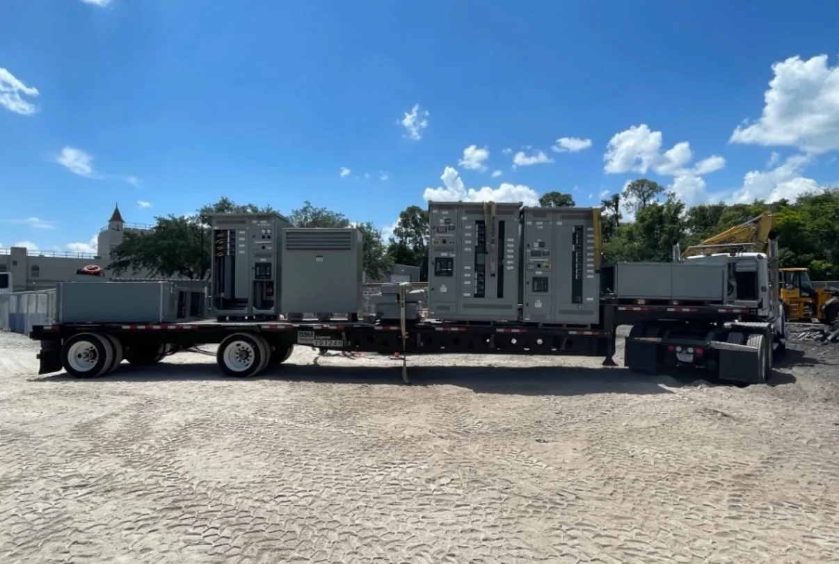
Automatic Transfer Switches for Ely Projects
An automatic transfer switch (ATS) connects a designated load to one of two power sources and changes the connection when its control system detects that the preferred source is outside configured limits. For an Ely facility, the right arrangement depends on the source types, the loads that need alternate power, and how the switch will interface with the rest of the electrical distribution system. A standby generator is one possible alternate source; another utility feeder or a different source arrangement may be appropriate in other designs. The equipment should be selected and specified for the actual project, not just by nominal voltage or a general expectation of backup operation.
Our U.S. manufacturing business builds new custom power-distribution equipment using all-American components and ships nationwide, including to Nevada. For a quotation, useful starting information includes the one-line diagram, system voltage and phase, available fault-current information, source details, load schedule, installation environment, and the required control and communications interfaces. Ratings, product configuration, listing status, and project suitability require confirmation by the equipment designer against the application.
Transition Behavior and Source Sensing — Automatic Transfer Switches in Ely, NV
Transfer transition describes how an ATS moves a load from one source to another. In an open transition, the switch disconnects the load from one source before connecting it to the alternate source. This is a common arrangement, but it may produce a brief interruption. A closed-transition arrangement momentarily connects sources together during transfer, where permitted and specifically engineered. That approach calls for careful review of source compatibility, synchronization, interconnection controls, and utility requirements. It should not be assumed suitable simply because reduced interruption is desirable.
Source-sensing settings determine when the controller treats a source as unacceptable and when it recognizes that source as restored. Voltage and frequency conditions, time delays, and the generator or upstream system’s response all affect transfer behavior. Settings should be coordinated with the source equipment and the facility’s operating requirements. A control sequence that reacts too quickly may lead to unnecessary transfers; one that waits longer may extend the interruption. The appropriate sequence is a design decision, not a universal factory setting.
Load, Continuous-Current, and Withstand Ratings
ATS selection requires more than matching a number on a nameplate to the facility’s system voltage. Voltage is a characteristic of the electrical system; equipment ratings describe limits and capabilities for the intended application. The switch’s current rating must account for the load it will carry, while the short-circuit withstand and closing capabilities must be evaluated in relation to available fault current and the specified upstream protective device. These ratings are distinct and should not be treated as interchangeable.
Load composition matters as well. Motors, transformers, electronic power supplies, and other loads can affect inrush, switching duty, and the acceptable transfer sequence. The design team should identify which loads are essential, whether they start together or in stages, and whether any loads should be excluded from the alternate source. Coordination with overcurrent protection and generator capacity can influence both ATS selection and the broader distribution design. Final ratings and coordination require review of project-specific electrical data.
Neutral Switching and Distribution Interfaces
Whether the ATS switches the neutral conductor depends on the grounding and bonding arrangement, source configuration, and applicable electrical design requirements. A solid, unswitched neutral and a switched-neutral configuration have different implications for how the sources relate to the load-side system. The choice should be made by the project’s qualified electrical professionals, considering the generator, service, grounding scheme, and other connected equipment. It should not be inferred from the switch’s pole count alone.
Other interfaces also need definition before equipment is released: source and load conductor entry, termination requirements, enclosure arrangement, control power, remote status points, and any building-management or generator-controller connections. The ATS may be part of a larger switchboard or installed as separate equipment, depending on the design. Space, access, routing, and coordination with adjacent gear affect the configuration. Clear interface information helps avoid mismatches between the switch, field wiring, source equipment, and distribution assembly.
UL 1008 and Project Verification
UL 1008 applies to transfer-switch equipment where required by the project and applicable requirements. It is a product standard for transfer equipment; it does not by itself establish that a particular ATS is suitable for every system, installation, or fault-current condition. Confirm the requested listing and configuration for the specific equipment being quoted. Do not assume that a standard reference, a voltage rating, or another product’s certification applies to a custom assembly or to every component in the electrical system.
Specification review should also address the transfer sequence, transition type, bypass or isolation needs if applicable, control features, enclosure requirements, and coordination with upstream and downstream equipment. Any requested listing, rating, or option must be verified for the offered configuration. Qualified engineers and the authority having jurisdiction can resolve requirements that depend on the complete installation.
Ely Site Conditions and Quotation Inputs
For an Ely installation, confirm site altitude and ambient conditions with the equipment designer, along with indoor or outdoor placement, enclosure exposure, ventilation, and the available installation space. Altitude and temperature may affect equipment performance or require derating; whether adjustments apply depends on the specific design and manufacturer’s limits. These conditions should be documented early rather than assumed from the city name.
Include shipping destination and site access constraints in the quotation request so the delivery plan can be considered without implying a particular arrival date. Provide the one-line diagram, source and load data, grounding information, fault-current study or other available fault data, environmental conditions, and required control interfaces. Our team manufactures new custom equipment in the United States and can review those inputs for a proposed ATS configuration. Final selection, settings, ratings, and installation details remain subject to project engineering and site review.