Utility Distribution Planning for Ely Projects
Utility electrical distribution work in Ely begins with the specific service and the requirements of the serving utility—not with a generic switchgear package. The interconnection point, ownership boundary and intended operating arrangement determine which equipment is needed and who must review it. A new service, a replacement lineup, a generation interconnection or a facility expansion can each bring different requirements for switching, metering, protection and control. Establishing those requirements early helps define a buildable scope and reduces the risk of late changes to the equipment arrangement.
For an Ely project, the electrical design team should also document the actual site elevation, expected ambient conditions, indoor or outdoor placement and enclosure environment. Elevation and temperature can affect equipment ratings or require design adjustments; the equipment designer should confirm whether derating or other measures apply to the specified installation. Local logistics matter too: access routes, unloading arrangements, laydown space and the path from delivery point to electrical room can influence dimensions and shipment planning. These details should be verified for the project rather than assumed from the city name.
Define the Interconnection and Metering Boundary
Before requesting a quotation, identify the service voltage and system configuration, available fault-current information, the point of common coupling and the demarcation between utility-owned and customer-owned facilities. The utility’s written service requirements and approved one-line diagram are key inputs. They can determine whether metering is utility-furnished, customer-furnished or coordinated across the boundary, as well as the location and accessibility of metering provisions.
Metering needs may affect compartment space, instrument-transformer provisions, terminal access and separation from other functions. The arrangement should be coordinated with the utility and the project engineer; a manufacturer should not infer meter type, ratios, wiring or acceptance criteria from a service voltage alone. If a project includes distributed generation, storage or alternate sources, the interconnection review may add requirements for isolation, directional protection, transfer schemes or controls. Those functions depend on the utility’s approved operating concept and applicable project documents.
Protection, Grounding and Coordination Choices
Protection design depends on system studies and the utility’s criteria. Specify the intended protective devices and functions, available fault-current data, coordination requirements, relay or trip-unit preferences, control-power needs and any communications interface. Selectivity, interruption capability and equipment withstand must be evaluated against the actual system conditions. A stated equipment rating is not the same as system voltage, and a rating by itself does not establish that a particular lineup is suitable for a site.
Grounding requires equal care. The one-line, grounding plan and utility requirements should identify the system grounding method, bonding points, ground-bus arrangement and connections to the site grounding network. Utility and customer grounding practices must be coordinated at the service boundary. A switchgear manufacturer can build to an engineered specification, but grounding and protection decisions require qualified electrical engineers, utility review and site-specific information.
Switchgear Configuration and Environmental Fit
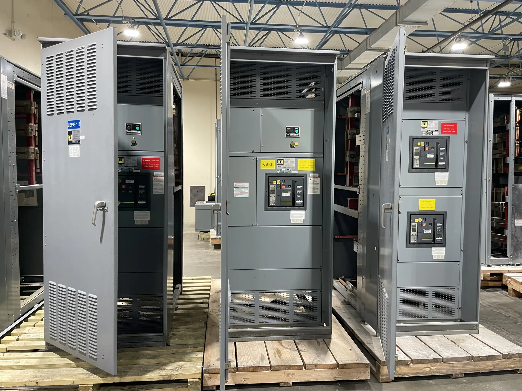
Configuration choices include main and feeder device arrangements, bus layout, compartment access, cable entry direction, termination space and provisions for future circuits. Each choice affects footprint, maintainability, installation interfaces and manufacturing scope. For an Ely facility, confirm room dimensions, door and aisle clearances, floor loading, cable trench or conduit locations, ventilation and exposure to dust or moisture. Outdoor equipment requires an enclosure and environmental specification suited to the actual installation; indoor equipment still needs conditions and access assessed.
Ratings and listings must be confirmed for the selected product and application. UL 891 applies to applicable low-voltage switchboards; it should not be treated as a blanket standard for every switchgear product or voltage class. Medium-voltage equipment, busway and other assemblies have different design and evaluation considerations. The project specification should state the required product type, voltage class, ratings, construction and any applicable listing or acceptance requirements, then have these details reviewed before release.
Inputs That Support a Useful Quotation
A complete quotation package typically includes the one-line diagram, equipment schedule, utility service requirements, system studies or available fault-current data, site and room drawings, environmental conditions, cable and conduit entry information, control schematics and the requested inspection or documentation scope. Note required interfaces with transformers, generators, protective relays, metering equipment and supervisory systems. Identify who supplies each component and who is responsible for integration, field connections and final acceptance.
Custom equipment is manufactured to the approved project requirements. This U.S. manufacturer uses all-American components, builds equipment in the USA and supports short lead times, with nationwide shipping available. Schedule expectations still depend on the finalized design, component requirements, engineering approvals and production coordination; no delivery date should be assumed until the project scope is reviewed.
Coordinate Utility Acceptance Before Release
Submit drawings and technical information through the project’s established utility and engineering review process. Confirm required witness points, inspection documents, labeling, test documentation and acceptance steps before fabrication, since late revisions can affect both configuration and schedule. The utility’s acceptance criteria are specific to its service and project; they should be obtained directly rather than inferred from another installation.
For an Ely utility project, a practical sequence is to establish the service boundary and site conditions, obtain the utility’s written requirements, complete protection and grounding design, and then finalize the equipment specification. Qualified engineers and the serving utility should resolve design questions, ratings and interfaces before the manufacturer releases the assembly for production. This coordination makes the equipment scope clearer for engineering, installation and eventual system integration.