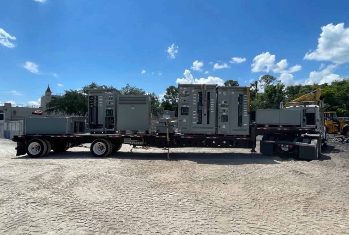
Medium-Voltage Switchgear for Elko, Nevada Projects
Medium-voltage switchgear is selected around the electrical system it must serve, not just a nominal voltage label. For an Elko project, the starting point is the one-line diagram and the utility or facility design information defining the system voltage, grounding arrangement, source configuration and intended switching functions. Those details guide the equipment arrangement and component selection. A manufacturer can build new custom equipment to a project specification, but the design must be reviewed against the actual site and electrical system before ratings or configuration are finalized.
Our U.S.-manufactured assemblies use all-American components, support short lead times and can ship nationwide, including to Nevada. Project-specific scope, engineering review and shipping arrangements affect the schedule; a delivery date should be confirmed for the particular order.
Define Voltage Class, Fault Duty and Insulation Requirements — Medium-Voltage Switchgear in Elko, NV
System voltage and equipment ratings are related but distinct. The system voltage describes the electrical network; the switchgear’s rated voltage and insulation level must be suitable for that network and its operating conditions. The specification should identify the applicable voltage class, maximum system voltage where required, and the insulation requirements established by the design. Naming a voltage alone does not establish a complete equipment rating.
Available fault duty is another essential input. The design team should provide the expected short-circuit conditions at the connection point and specify the interrupting and withstand capabilities needed for the system. These requirements must align with the source, transformers, connected equipment and protective-device coordination. A fault-duty value should not be guessed from a service description or copied from an unrelated project.
Choose Protective Relays and Switching Functions for the Scheme
Relay selection follows the protection philosophy and the functions required by the one-line diagram. Depending on the design, the specification may address overcurrent protection, ground-fault elements, voltage or frequency functions, transformer protection interfaces, metering, communications and breaker control. Not every application needs the same functions, and relay features must be coordinated with current transformers, voltage transformers, breaker trip circuits and the facility’s monitoring or control system.
Ask the engineer to identify required settings responsibility, communications protocol, control power and any alarm or status points that must interface with other equipment. Protection coordination requires system data and review by qualified electrical professionals. The switchgear manufacturer can build to confirmed requirements, but cannot establish a suitable protection scheme without the relevant design information.
Plan Cable Terminations, Enclosure and Elko Site Conditions
Cable entry and termination details shape compartment layout and field installation. Quotation documents should show cable type and size, number of runs, conductor material where specified, entry direction, termination method and available bending space. Include the connected equipment and any bus or cable interfaces so that physical clearances and connection points can be reviewed before fabrication. Termination arrangements must be compatible with the selected components and the installer’s approved design.
For an Elko site, document the actual ambient conditions and installation environment rather than relying on a citywide assumption. Specify indoor or outdoor placement, enclosure needs, exposure to dust or moisture, elevation or temperature conditions if relevant to the project, and any ventilation or environmental controls. Also provide the room or pad layout, access routes, working clearances and maintenance access expected by the facility design. These conditions can affect enclosure construction, component selection and equipment arrangement.
Coordinate Interfaces, Clearances and Maintenance Access
Medium-voltage switchgear is part of a larger electrical installation. Confirm how it connects to incoming sources, transformers, downstream distribution, grounding, control power and communications. The project team should resolve conduit or cable routes, interface dimensions, foundation requirements, door and panel clearances, and access for inspection or component service. Constraints in an existing electrical room may influence the lineup configuration; dimensions and photographs can help communicate conditions, but do not replace verified site measurements.
Maintenance planning should inform the arrangement from the outset. Identify which compartments and components require access, how equipment will be approached, and whether adjacent walls or other systems limit service space. Final access and installation requirements depend on the equipment design, applicable codes and standards, and site review by qualified professionals. They should not be inferred from a generic product description.
Prepare a Complete Specification for a Project Quote
For a useful quotation, provide the latest one-line diagram, equipment schedule, applicable specifications and available system studies. Include system voltage and grounding, fault duty, insulation requirements, lineup configuration, protective-relay functions, cable termination data, enclosure and environmental conditions, control and communications interfaces, and project dimensions. Note any required drawings, submittal milestones, inspection or testing scope, and delivery destination. Ratings, listings and project details require confirmation against the final specification and design.
UL 891 applies to applicable low-voltage switchboards; it should not be treated as a standard covering medium-voltage switchgear. Any requested listing or standards requirement must be stated for the specific equipment and verified during engineering review. With complete inputs, the manufacturer can assess the requested configuration, identify open questions and develop a quote for new custom equipment intended for the Elko project.