Low-Voltage Switchgear Planning for Dayton, Nevada
Low-voltage switchgear for a Dayton project should be selected around the electrical system it must serve, the way the facility operates, and the conditions at the installation site. Start with the one-line diagram, available fault-current information, system grounding, load profile, and the required incoming and outgoing circuits. These details help engineers determine whether a low-voltage power circuit breaker arrangement fits the project and what ratings, protective functions, and enclosure configuration need to be evaluated. A product rating is not the same as system voltage, and neither can be established from a location name alone.
Our U.S. manufacturing business builds new custom power-distribution equipment using all-American components. We manufacture equipment for customer projects and ship nationwide, including to Nevada. A quotation begins with the project requirements; it does not substitute for review by the responsible electrical engineer or confirmation of the installation site.
Compare Power Circuit Breaker Arrangements — Low-Voltage Switchgear in Dayton, NV
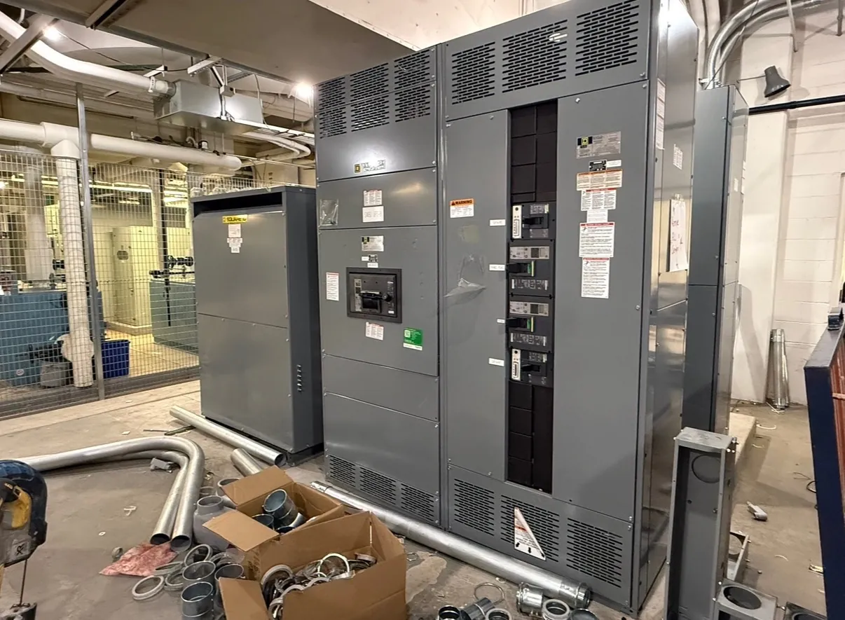
Low-voltage power circuit breakers may be arranged in ways that affect equipment footprint, access, serviceability, and how the lineup interfaces with the rest of the distribution system. The right choice depends on the project’s operating needs and the manufacturer’s design for the specified equipment—not on a general preference for one arrangement. Discuss whether the design calls for drawout or fixed breaker construction, how many breaker positions are required, and whether future circuit provisions are part of the scope.
For each feeder and main position, provide the intended function, load information, protective-device requirements, and available system data. Breaker frame and trip details must be coordinated with the electrical design and verified against the equipment configuration. Changes to circuit count or breaker arrangement can affect the lineup’s dimensions, connections, and service access, so these choices are best settled before fabrication drawings are developed.
Bus Ratings and Protective Coordination — Low-Voltage Switchgear in Dayton, NV
Bus selection involves more than choosing a number on a schedule. The engineer must establish the required continuous-current rating and evaluate the assembly’s short-circuit withstand or interrupting requirements in the context of the complete system. Those ratings depend on the project’s electrical data and the specific equipment design. Confirm the system voltage separately; a bus or breaker rating should not be treated as a statement of system voltage.
Protective coordination also shapes the design. The engineer should review the upstream and downstream protective devices, available fault current, time-current settings, and the facility’s desired selectivity where applicable. Coordination objectives can involve tradeoffs between maintaining service to unaffected circuits and limiting fault duration. Provide current studies and device information when available, and identify any required revisions or study responsibilities in the project documents. Final selections require qualified engineering review rather than assumptions based on a preliminary product description.
Maintainability and Site Access in Dayton
Consider how technicians will reach breaker compartments and service areas over the life of the equipment. Working space, access routes, door movement, adjacent equipment, and the planned means of moving sections into position can influence lineup layout. Site review should establish the actual installation area and applicable working-space requirements; a nominal equipment outline alone does not confirm that the finished installation will fit or remain accessible.
For a Dayton delivery, site and logistics details should be confirmed with the project team. Review building access, delivery restrictions, receiving hours, unloading arrangements, and the route from the receiving point to the electrical room. These conditions can affect how the equipment is divided for shipment and the sequence for setting and joining sections. No particular site condition should be assumed without customer-provided information.
Floor Loading, Cable Entry, and Installation Sequence
Floor capacity and equipment weight need attention early, especially when the switchgear will be placed in an existing electrical room or on a structure with defined load limits. Provide available floor plans, structural information, room dimensions, and any limits on concentrated loads for evaluation by the project’s qualified design professionals. Equipment dimensions and weights must be confirmed for the final configuration rather than inferred from a typical lineup.
Specify top or bottom cable entry as required by the room design, and identify cable direction, conductor information, termination space, and any constraints imposed by ducts, trenches, or overhead routing. These interfaces can affect compartment layout and access. Also describe the intended installation sequence: where sections will be received, how they will be moved, and whether the room must remain accessible to other trades. Confirm these plans with the site team before the equipment arrangement is finalized.
Project Information for a Useful Quotation
To begin a Dayton low-voltage switchgear quotation, share the one-line diagram, equipment schedule, system voltage, required bus and breaker ratings, fault-current and coordination information, and the desired breaker arrangement. Include enclosure and cable-entry requirements, available room drawings, floor-loading information, and known delivery or installation constraints. Identify the governing project specifications and any requested standards or listing requirements. UL 1558 may be relevant to low-voltage metal-enclosed switchgear, but applicability and any specific listing must be confirmed for the product and project; it should not be assumed from a general description.
We can use the supplied requirements to develop a project-specific equipment proposal and clarify open design inputs. Ratings, construction details, standards, listings, and interfaces remain subject to confirmation against the final engineering documents and site conditions before manufacture.