Planning Switchgear for a Dayton, Nevada Project
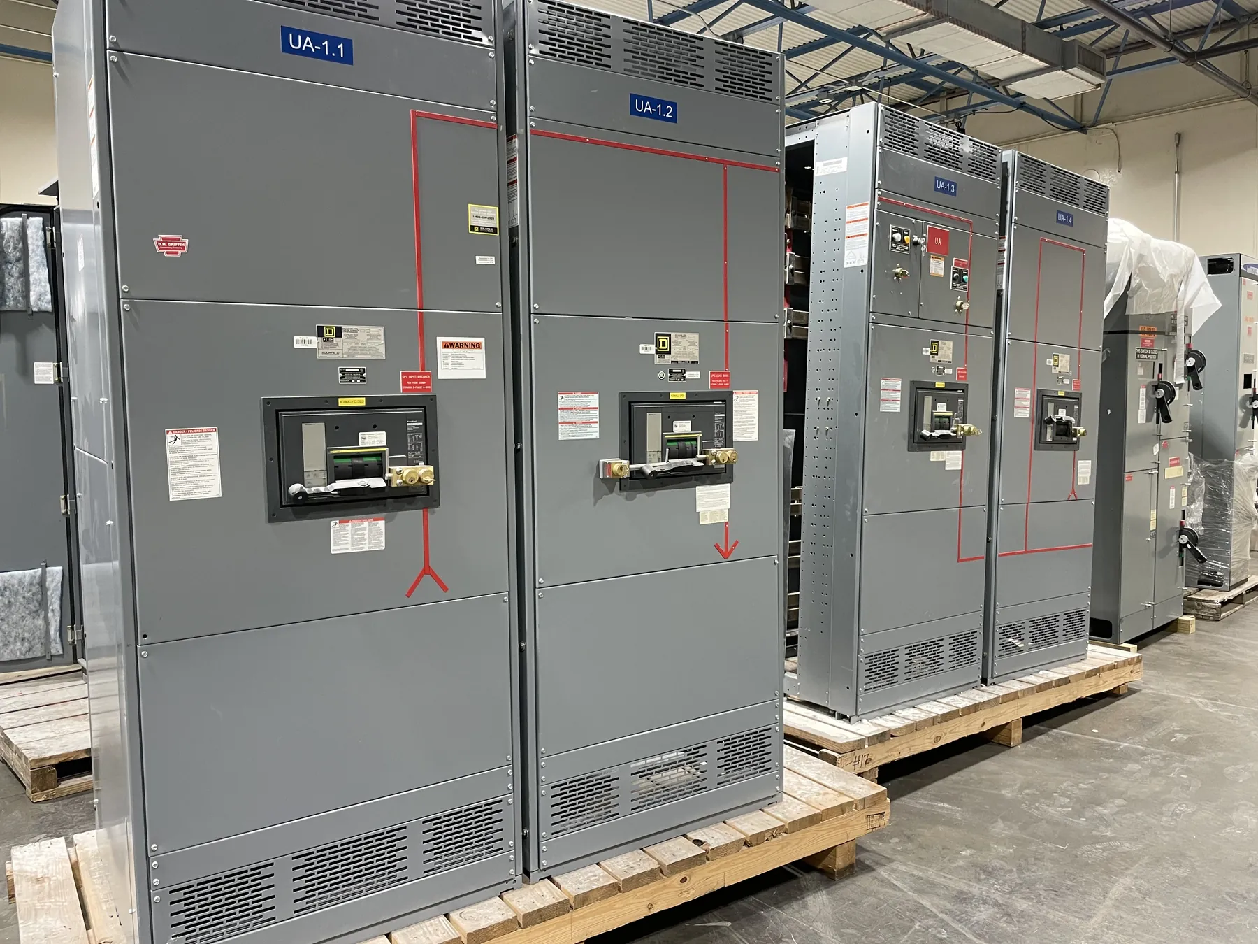
Specifying distribution equipment for a Dayton project starts with the electrical design and the conditions at the installation site. The one-line diagram, load information, available fault-current data, source arrangement and downstream equipment all help define what the assembly must do. The project team should also identify whether the equipment is a low-voltage switchboard, switchgear assembly or another distribution product; those terms are not interchangeable, and the applicable design and listing requirements depend on the product. A U.S. manufacturer can build new custom equipment for shipment to Nevada, but the design, ratings and project interfaces need review before they are finalized.
Begin with the intended system voltage and the equipment ratings as separate specification items. Voltage describes the electrical system; ratings describe the limits and capabilities assigned to the equipment and its components. The engineer of record should determine the required ratings from the system study and project documents. Do not assume a rating from a similar installation or from a product description. For applicable low-voltage switchboards, UL 891 may be relevant; it does not apply to every type of switchgear or to medium- and high-voltage products. Confirm the intended product category, listing requirements and configuration during engineering review.
Resolve Cable Entry and Electrical Interfaces Early
Cable entry can shape the lineup layout, cabinet arrangement and installation sequence. The project documents should state whether conductors enter from above or below, where the equipment will sit relative to conduits or cable tray, and which sections need access for incoming and outgoing connections. Include conductor sizes and quantities when established by the electrical design, along with lug requirements, termination space, neutral and grounding provisions, and any transition or connection points to adjacent equipment. These details should be verified against the manufacturer’s drawings and the site routing plan rather than assumed from a nominal enclosure size.
Check for conflicts between cable pathways and building conditions: beams, overhead services, slab penetrations, walls, doors and nearby equipment can affect access and routing. If the final conduit locations are not available at quotation, identify them as pending and agree on when they must be resolved. A late change to entry direction or connection locations may require a revised arrangement and can affect manufacturing documents, so clear interface ownership helps keep design coordination orderly.
Account for Floor Loading, Access and Working Space
Before selecting a final lineup arrangement, confirm the available floor area, support conditions and handling route. The project engineer and building team should review floor capacity against the equipment information provided for the proposed configuration. Consider the equipment footprint, section arrangement, anchorage requirements and any raised floor or housekeeping pad. Do not infer actual weight or loading from a preliminary layout; request the relevant manufacturer data for the specified design and have the responsible professionals evaluate it for the site.
Working space is another design constraint, not just a dimension on a plan. The electrical designer should determine required clearances and access in accordance with the applicable codes, equipment instructions and site conditions. Review door swing, aisle width, egress, ventilation, access to cable compartments and the ability to bring sections into the room. Dayton-area facilities may have different room layouts, access roads and receiving constraints, so verify these details for the actual project rather than relying on a generic site assumption.
Coordinate the Installation Sequence and Delivery
Define how the equipment will move from receiving to its final position. Confirm unloading responsibility, available lifting or moving equipment, door and corridor dimensions, turning space, floor transitions and whether the lineup can be moved as an assembled unit or must be handled in sections. The manufacturer’s approved shipping configuration and handling information should guide planning. Building access, weather exposure during receiving and the interval between delivery and placement are practical considerations for a Nevada site; protect equipment as directed by the manufacturer and keep it in suitable storage conditions.
Work backward from the planned installation sequence when setting project milestones. Establish when room readiness, foundations or pads, conduit stubs, cable routes and adjacent equipment interfaces must be confirmed. Coordinate the desired delivery window with site readiness and receiving capability. Nationwide shipping from a U.S. manufacturer can support a Dayton project, but transit arrangements and timing depend on the order and should be confirmed for that project; no local facility or fixed delivery schedule should be presumed.
Prepare a Complete Quotation Package — Switchgear for Dayton, NV
A useful request for quotation includes the one-line diagram, equipment schedule, system and rating requirements, available fault-current information, source and load arrangement, required product type, environmental conditions and applicable project specifications. Add a plan view or room layout with dimensions, cable-entry direction, conduit locations, working-space constraints, floor or support information, and the intended installation sequence. Identify required metering, protective devices, communications, accessories and connection interfaces only as defined by the project design.
Also note which details are firm and which remain subject to engineering or site confirmation. The manufacturer can use that distinction to identify open questions before layout development and to state what assumptions inform its proposal. Custom equipment is built to the approved project configuration, so changes to ratings, entry points, dimensions or interfaces should be reviewed before release for manufacture.
Review Drawings Before Dayton Installation
After proposal review, compare the equipment drawings with the latest electrical and architectural documents. Confirm lineup dimensions, section functions, access, cable termination locations, interfaces to upstream and downstream equipment, and the room’s clearances. The electrical engineer and other responsible project professionals should resolve any conflicts and verify that the proposed arrangement meets the project requirements. Ratings, listings and final configuration all require confirmation for the specific equipment and application.
U.S.-built custom distribution equipment with all-American components can be specified for projects in Dayton and shipped nationwide. The most reliable path from quotation to installation is careful coordination among the design team, manufacturer, contractor and site personnel—especially around cable entry, floor conditions, working space and delivery sequence. Once those project details are aligned, the equipment can be developed for the intended installation rather than selected on assumptions.