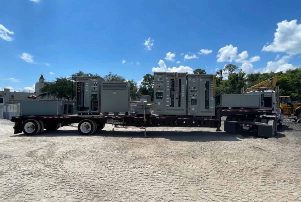
Low-Voltage Switchboards for Dayton, NV Projects
Low-voltage switchboards distribute power from a service or upstream source to downstream feeders and loads. For a Dayton project, the right arrangement depends on the electrical system, the equipment being served, available installation space, and the design documents—not simply on a nominal voltage or a preferred enclosure size. A custom switchboard can be configured around the project’s service and feeder requirements, with component selection and ratings reviewed against the application.
We manufacture new custom power-distribution equipment in the United States using all-American components, and ship nationwide, including to Nevada. Project-specific engineering and documentation are essential: the equipment configuration, applicable listings, ratings, and interfaces must be confirmed for the intended installation.
Service and Feeder Arrangements Start with the One-Line
The one-line diagram establishes how the switchboard fits into the distribution system. It identifies the source, service or distribution function, protective devices, and outgoing feeders. The design team should clarify whether the board is intended for service equipment or for downstream distribution, and identify the loads, feeder destinations, and any planned future circuits. These choices affect the lineup, device arrangement, conductor connections, and the information needed for a complete quotation.
Feeder arrangement is also a physical coordination issue. Breaker or other device positions, cable termination locations, and access for incoming and outgoing conductors should reflect the electrical drawings and the room layout. Changes in circuit count or feeder routing can affect section dimensions and cable space, so late revisions may require a design review rather than a simple substitution.
Bus Sizing, System Voltage, and Available Fault Current
Bus requirements should be based on the project’s specified load and applicable design criteria. The bus rating is not the same thing as system voltage: voltage describes the electrical system, while equipment ratings address particular limits and functions. Neither should be inferred from the other. The engineer of record and equipment manufacturer need the design basis to determine whether the proposed arrangement is appropriate.
Available fault current at the switchboard is a key coordination input. The specified short-circuit rating and protective-device arrangement must be evaluated in relation to the source and the rest of the system. A higher nominal system voltage alone does not establish the fault-current requirement, and a device rating cannot be assumed to make the complete assembly suitable. Provide the available-fault-current information or the engineering assumptions used to establish it, along with upstream protective-device details. Final suitability requires qualified engineering review and confirmation against project documentation.
When UL 891 May Apply—and What to Document
UL 891 applies to applicable low-voltage switchboards; it should not be treated as a blanket standard for every switchgear product or electrical assembly. Whether it applies depends on the equipment type and project scope. It does not establish the rating or suitability of an individual board by itself, and it does not apply to medium- or high-voltage equipment, busway, or every product category.
For a Dayton specification that calls for a UL 891 switchboard, the submittal should identify the applicable product and provide project-specific listing documentation for the proposed assembly. Confirm the listing scope, equipment configuration, ratings, and any specified options with the manufacturer and project team. Do not assume that one listing statement covers every section, device, rating, or installation condition. The electrical engineer and authority having jurisdiction determine project requirements and acceptance.
Dayton Installation Planning: Entry, Floor, and Working Space
Before the lineup is finalized, compare the switchboard layout with the actual room or electrical area. Cable entry direction and termination space should match the planned conduit or cable routes. Confirm whether conductors enter from above, below, or another designated approach, and check that bends and terminations can be accommodated without conflicting with adjacent equipment or building features.
Floor loading and the proposed equipment footprint also require review. The project team should verify that the supporting floor and any access route are suitable for the specified assembly and installation method. Working space must be coordinated with applicable code requirements and the site plan; it should not be reduced based on assumptions about how the equipment will be accessed. Local conditions such as room dimensions, doorways, obstructions, and the sequence of other trades can affect delivery and placement planning.
Quotation Inputs and the Desired Installation Sequence
A useful quotation package includes the latest one-line diagram, equipment specifications, system voltage, bus requirements, available fault current, upstream protective-device information, feeder schedule, cable-entry preference, and project-specific listing requirements. Include room drawings or dimensions, floor and access constraints, and the desired installation sequence. Note whether the switchboard must interface with existing equipment or fit a defined project phase. These inputs allow the proposed design and submittal scope to be reviewed before release for manufacture.
Manufacturing is based on confirmed project requirements, not on a generic Dayton configuration. Lead time depends on the finalized design, component selection, and project coordination; timing should be confirmed for the specific order. Early communication about feeder changes, building access, and installation sequence helps the team resolve interface questions before they affect the equipment layout or schedule.