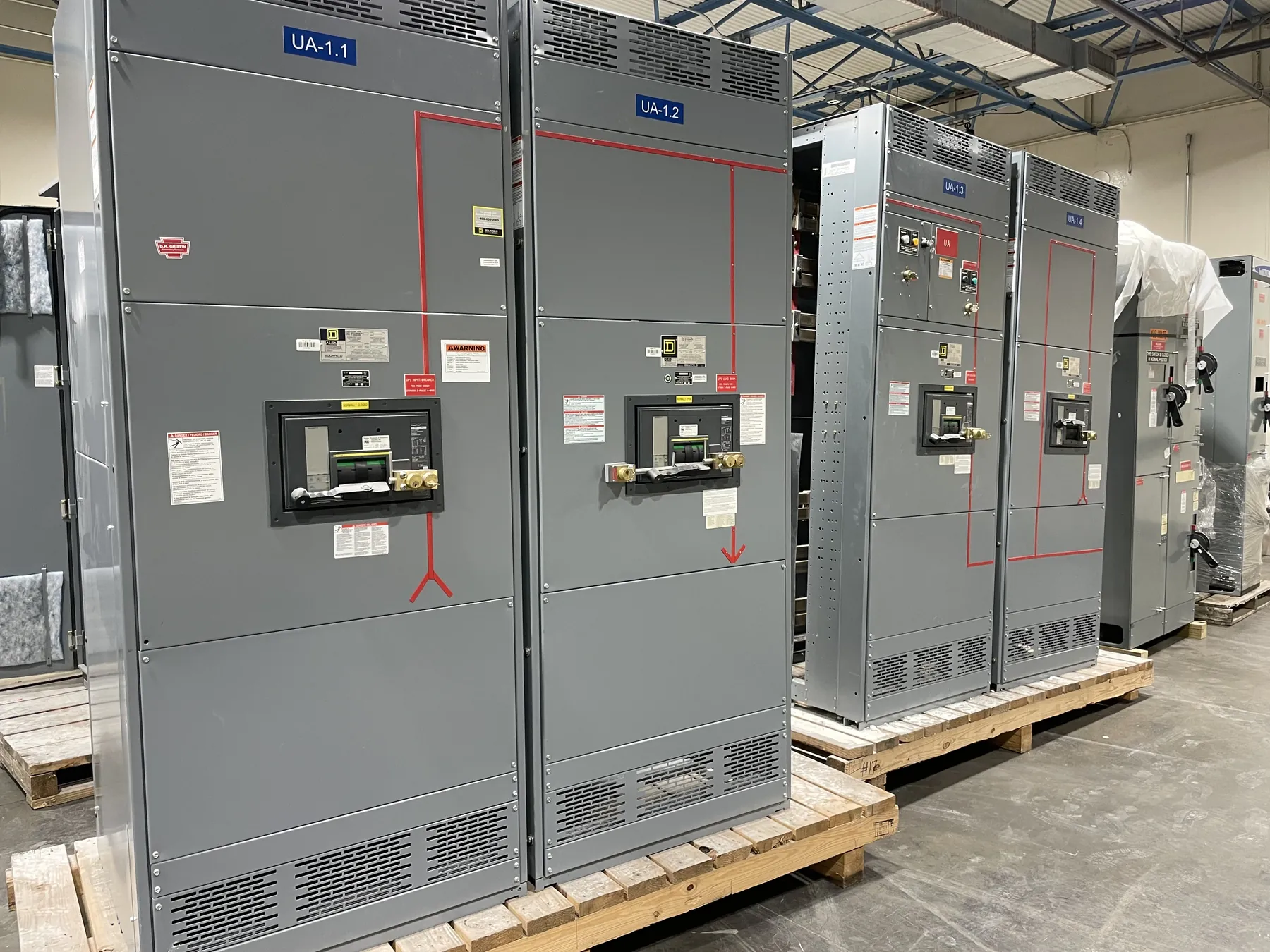
Metal-Clad Switchgear for Dayton, Nevada Projects
Metal-clad switchgear is a medium-voltage equipment arrangement in which major components are separated into grounded metal compartments. That construction helps contain and organize the breaker, bus, instrument transformers, and cable connections, but it does not by itself determine a project’s safety, suitability, or performance. Those depend on the equipment design, system conditions, protection scheme, installation, and operating requirements. For a Dayton project, the first step is to define what the switchgear must connect, control, and protect, then confirm those details with the responsible electrical engineer.
We manufacture new custom switchgear and power-distribution equipment in the United States using all-American components. We serve Nevada projects and ship nationwide. A quotation can be developed around the project’s electrical design and physical constraints; the final configuration, ratings, applicable standards, and any listing requirements must be confirmed for the specific assembly and application.
Compartmentalization and Withdrawable Breaker Choices — Metal-Clad Switchgear in Dayton, NV
Compartmentalization affects both equipment layout and maintenance planning. A typical metal-clad design separates the main bus, circuit breaker, and cable or termination areas, with additional compartments and barriers determined by the selected arrangement. The project team should establish which components require access, how circuits are grouped, where metering and protection devices belong, and whether future circuit additions are part of the plan. More compartments can support separation and defined access, while also affecting lineup dimensions, interfaces, and cost.
Withdrawable breakers allow a breaker to be moved between defined connected, test, and disconnected positions within its cubicle. The mechanism, interlocks, shutters, and control connections must be coordinated as part of the complete design. Breaker selection should reflect the system’s nominal voltage and operating conditions, as well as required continuous-current and interrupting ratings. These ratings are not interchangeable with system voltage, and neither should be selected from a general product description alone. Qualified engineering review is needed to verify them against the project’s fault study and equipment schedule.
Grounding, Protection, and Relay Coordination — Metal-Clad Switchgear in Dayton, NV
Grounding arrangements influence how ground faults are detected and cleared. The equipment design must align with the system grounding method, available ground-fault current, and the protection devices specified for each circuit. Ground buses, cable grounding provisions, instrument-transformer connections, and any neutral or grounding equipment should be documented at the design stage. The switchgear cannot establish a correct grounding strategy independently of the facility’s electrical system.
Relay coordination is a system-level task: protective devices should operate in an intentional sequence so that a fault is cleared by the appropriate device while other parts of the system remain protected. That work depends on verified relay functions and settings, breaker operating characteristics, instrument-transformer ratios, available fault current, and upstream and downstream devices. Provide the engineer’s coordination study or design criteria when available. Changes to feeder loads, transformer data, utility characteristics, or protective-device selections may require the study and settings to be revisited.
Applying IEEE C37.20.2 to the Project — Metal-Clad Switchgear in Dayton, NV
IEEE C37.20.2 is the standard for metal-clad switchgear and control assemblies. Its applicability should be evaluated against the specified assembly type and project requirements rather than assumed from the phrase “metal-clad.” The specification should identify the required edition or project basis, applicable ratings, construction requirements, and any contractual testing or documentation expectations. Confirm that the proposed equipment falls within the standard’s scope; do not treat it as a substitute for system engineering, installation requirements, or other applicable codes and standards.
Ratings, standard conformance, and listings are separate matters that require confirmation for the actual product and intended use. Where a project requires a particular listing or other approval, state it in the equipment specification so it can be reviewed during design. Final acceptance depends on the assembly and project details, not simply on a general reference to IEEE C37.20.2.
Dayton Site Conditions and Installation Sequence
For a Dayton facility, shipping access and site conditions should be reviewed early without assuming a particular route, unloading arrangement, or building layout. Share the delivery access constraints, receiving hours, unloading resources, and any restrictions on moving equipment from the receiving point to its final location. The delivery plan should match the equipment’s shipping sections and the site’s handling capabilities; those details need confirmation during project planning.
Floor loading and anchorage require review against the building structure and the equipment arrangement. Include available floor plans, structural criteria, housekeeping-pad details if applicable, and the intended lineup location. Cable entry is another key interface: identify top or bottom entry preferences, cable direction, termination space, cable types and sizes when known, and the routing approach. Working space, door or panel access, ventilation, and nearby obstructions should also be checked against the applicable design and installation requirements by qualified project personnel.
Define the desired installation sequence before the lineup is finalized. A project may need equipment delivered in sections, staged in a particular area, or installed around other construction work. State what must be in place before delivery, how the switchgear will be positioned, and which connections or control interfaces depend on other trades. These inputs can affect section breaks, shipping configuration, cable compartments, and documentation.
Information for a Dayton Switchgear Quotation
Useful quotation inputs include a one-line diagram, system voltage, available fault-current information, feeder and main-device schedules, grounding method, relay and metering requirements, and the project’s preferred equipment arrangement. Include indoor or outdoor installation conditions, cable-entry needs, physical dimensions or room drawings, floor-loading constraints, working-space requirements, desired installation sequence, and specified standards or listing requirements. Identify required interfaces with transformers, generators, utility connections, control systems, and downstream equipment.
Complete information helps establish a practical design basis, but it does not replace engineering review. We can manufacture new custom equipment to the confirmed project requirements, with short lead times supported by the manufacturer and shipment available nationwide. Actual lead time, final ratings, applicable standards, and delivery planning are confirmed for the defined scope.