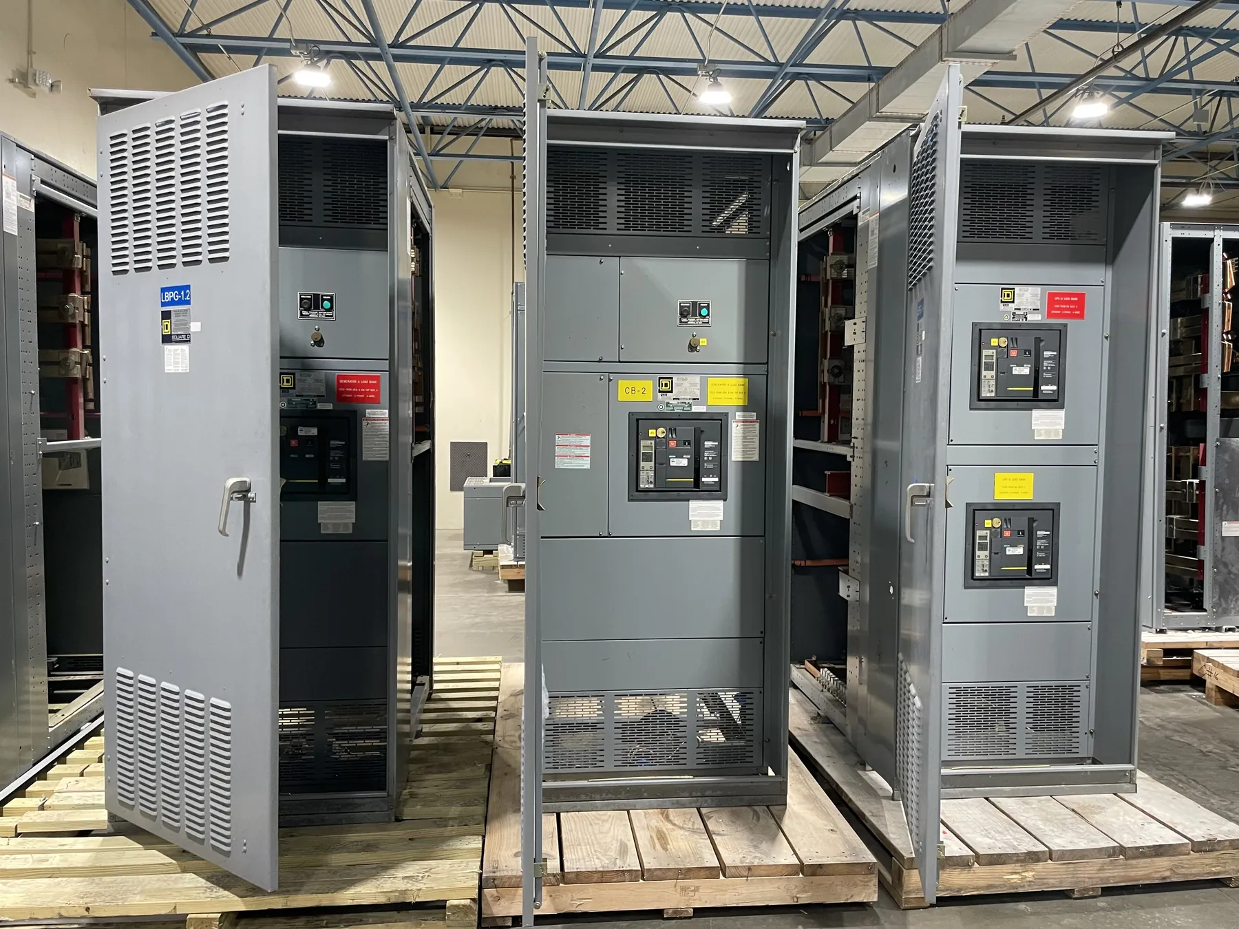
Automatic Transfer Switches for Dayton Projects
An automatic transfer switch (ATS) moves a designated load between normal and alternate power sources when its controls detect a qualifying change in source conditions. For a Dayton facility, the right arrangement depends on what must remain supplied, which sources are available, how the load behaves during an interruption, and how the switch will fit into the electrical distribution system. A custom-built assembly can be configured around project requirements, but equipment ratings, applicable listings, and the final design must be confirmed by qualified engineers using site and system information.
Transfer is not the same as generating backup power. The ATS monitors and selects between sources; a generator or other alternate source must be provided and coordinated separately. The design should establish which loads transfer, what conditions initiate transfer, and whether restoration to the normal source should occur automatically after it is acceptable. Those choices affect controls, source interfaces, downstream distribution, and the sequence of operation.
Transition Choices and Source Sensing
With an open-transition arrangement, the switch disconnects one source before connecting the other. This avoids intentionally paralleling the sources, but produces an interruption during transfer. A closed-transition arrangement briefly overlaps sources only when system design and controls permit it; it requires careful coordination with the sources and the applicable utility or facility requirements. Neither approach is universally preferable. Load sensitivity, source characteristics, operating policy, and approval requirements guide the selection.
Source sensing determines how the ATS recognizes an unacceptable source and when it may transfer or retransfer. The project team should define the monitored conditions and acceptable thresholds rather than assume a default setting suits the facility. Generator starting and stabilization delays, transfer and retransfer timing, and any inhibit or test inputs should be coordinated with the generator controls and the intended operating sequence. The switch’s control logic must reflect the actual source arrangement, not simply the nominal system voltage.
Load, Withstand, and System Ratings — Automatic Transfer Switches in Dayton, NV
ATS selection requires more than matching a nameplate number to the service. The continuous current rating must suit the connected load and installation, while the equipment’s short-circuit withstand and closing capability must be appropriate for the available fault current and the upstream protective device. These ratings describe different characteristics; they are not interchangeable, and neither should be inferred from system voltage. Confirm the system configuration, calculated fault conditions, protective-device type and settings, and coordination requirements with the responsible electrical engineer.
Load characteristics matter as well. Motor starting, transformer energization, non-linear loads, and loads that cannot tolerate a momentary interruption may influence switch selection, control settings, or the overall transfer scheme. A downstream load list and the intended grouping of essential and nonessential circuits help establish whether one ATS or multiple transfer points are appropriate. Ratings and product details require review against the project documents and the specific equipment configuration.
Neutral Switching and Grounding Coordination — Automatic Transfer Switches in Dayton, NV
Whether the neutral is switched is an application decision tied to the source and grounding arrangement. A separately derived generator system, the location of neutral-to-ground bonding, and the number of transfer sources can affect the required neutral configuration. Incorrect assumptions can create grounding and protection concerns, so the ATS neutral arrangement must be reviewed alongside the one-line diagram and grounding design by qualified engineers. A four-pole switch is not automatically required for every generator installation, nor should a solid neutral be presumed suitable for every system.
Provide the manufacturer with the source configuration, grounding and bonding details, conductor arrangement, and any project requirements for neutral switching. This information helps prevent a mismatch between the specified transfer equipment and the engineered system. UL 1008 applies to transfer-switch equipment where required; its applicability and the exact listing status must be verified for the particular product and project. It should not be treated as a blanket certification of the complete installation or of unrelated distribution equipment.
Dayton Site Fit, Access, and Installation Sequence
For a Dayton project, enclosure and installation planning should account for the actual electrical room or outdoor location, not just a drawing footprint. Confirm cable entry direction, conductor bending and termination space, route conflicts, door access, environmental exposure, and the required working space. Floor loading and anchorage should be checked against the selected assembly and site conditions by the project team. These details can affect enclosure dimensions, termination layout, and the sequence for moving equipment into position.
Agree on the desired installation sequence before release for manufacture. The sequence may depend on when the enclosure can be placed, when feeders and control wiring are available, and how the ATS will be integrated with the normal source, generator, and downstream loads. Shipping to Dayton can be coordinated as part of a nationwide delivery plan, but site access, receiving arrangements, unloading, and placement are project-specific and should be established with the responsible contractors.
Information for a Dayton ATS Quotation
A useful quotation package includes the one-line diagram, system voltage and phase, source and generator information, load schedule, required current and short-circuit ratings, protective-device details, and the proposed transfer sequence. Include neutral and grounding requirements, control interfaces, enclosure location, cable entry preferences, and any applicable project specifications. Drawings and site dimensions help identify installation constraints early. Assemblies use all-American components and are built in the USA, with short lead times supported and nationwide shipping available; the actual configuration, schedule, and project requirements must be confirmed during review.