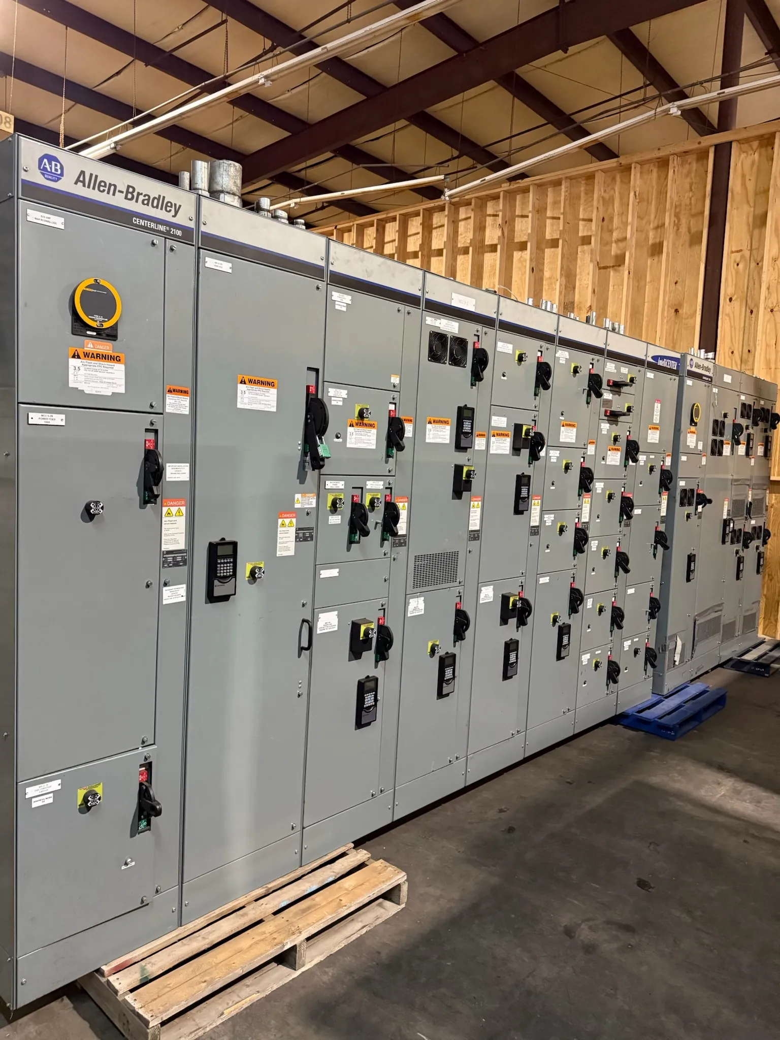
Casino Electrical Distribution for Dayton, Nevada Projects
Casino facilities combine public spaces, gaming areas, food service, back-of-house operations and building systems that may have different power priorities and maintenance constraints. A distribution design for a Dayton project should begin with the facility’s operating needs, the electrical design basis and the planned phases of construction or renovation. Custom switchboards and related power-distribution equipment can be configured to suit project requirements, but the appropriate arrangement, ratings and applicable listings must be established through engineering review.
Separate critical, life-safety and general loads in the design documents rather than relying on broad labels alone. Identify which loads are required to remain available, which are served by emergency power, and which can be interrupted under an approved maintenance or operating plan. The electrical engineer and facility team can then coordinate equipment sections, feeders, protective devices and source connections with the project’s one-line diagrams and operating intent.
Load Priorities and Emergency-Power Interfaces
Emergency-power coordination affects more than the location of a connection. The design team should document the source arrangement, transfer equipment, distribution boundaries and loads assigned to each source. Switchgear and switchboard interfaces must align with the project design; the equipment supplier should not be expected to determine life-safety classifications, emergency-power requirements or code interpretations without qualified engineering direction and site review.
For casino projects, confirm how emergency and standby loads interact with essential building functions and operational systems. Some loads may be required to transfer together, while others may have distinct source or sequencing requirements. Provide the intended transfer scheme, available fault-current information, protective-device coordination requirements and any project-specific control interfaces during design review. Ratings are not interchangeable with system voltage, and equipment ratings and product applicability require confirmation against the actual electrical conditions.
Phased Maintenance and Continuity Planning
Renovations and planned maintenance can take place around active facility operations, making access to equipment and the intended installation sequence important early decisions. Share the proposed shutdown windows, temporary-power assumptions, boundaries between existing and new distribution, and the order in which equipment sections or feeders will be installed. These details help the project team assess whether the proposed arrangement supports the work plan; they do not replace a site-specific outage and safety plan.
Where future expansion or staged construction is anticipated, identify which spaces, feeders or sections are part of later phases. The design team can evaluate how spare provisions, cable routing and equipment grouping fit the project’s long-term plan. Any spare capacity, future-ready feature or maintenance arrangement should be defined and verified in the project documents rather than assumed from a general equipment description.
Dayton Site Conditions and Installation Planning
For a Dayton installation, review the actual delivery route and building conditions rather than assuming that equipment can reach its final location without constraints. Confirm access dimensions, unloading and movement arrangements, room layout and the desired installation sequence with the contractor and site team. Nevada project logistics should be coordinated with the construction schedule, site access requirements and the manufacturer’s shipping plan; a specific delivery date or local facility condition cannot be assumed without project information.
Room and equipment details also affect configuration. Provide cable entry direction and routing expectations, available working space, floor loading information and any restrictions on moving or positioning sections. The electrical engineer and responsible project professionals should confirm that the proposed equipment arrangement fits the site, complies with applicable requirements and supports the intended maintenance access. These conditions can influence section dimensions, entry provisions and the sequence in which equipment is placed and connected.
Information for a Project-Specific Quotation — Casino Switchgear in Dayton, NV
A useful quotation package includes the current one-line diagram, equipment schedule, system voltage, required ratings, source and feeder details, and the stated division of critical, life-safety and general loads. Include the emergency-power and transfer interfaces, metering or control requirements, cable entry preferences, available room and working-space information, floor loading criteria, and project phasing or installation milestones. Applicable specifications and required product listings should be identified for review.
These inputs allow the manufacturer to evaluate the requested configuration and flag information that needs clarification. UL 891 applies to applicable low-voltage switchboards; it should not be treated as a blanket listing for all switchgear or other equipment. The requested product type, ratings, listings and project details must be confirmed for the specific design. Final equipment selection and electrical design remain subject to qualified engineering review and site conditions.
New Custom Equipment for Nevada Casino Projects
We manufacture new custom switchgear and power-distribution equipment in the United States using all-American components, and ship nationwide, including to Nevada. Short lead times are a stated manufacturing capability, not a promised schedule for a particular project; timing depends on the finalized scope and project requirements. For a Dayton casino project, early coordination of load priorities, emergency-power interfaces, cable entry, room conditions and phased work helps establish a more complete basis for equipment review and quotation.