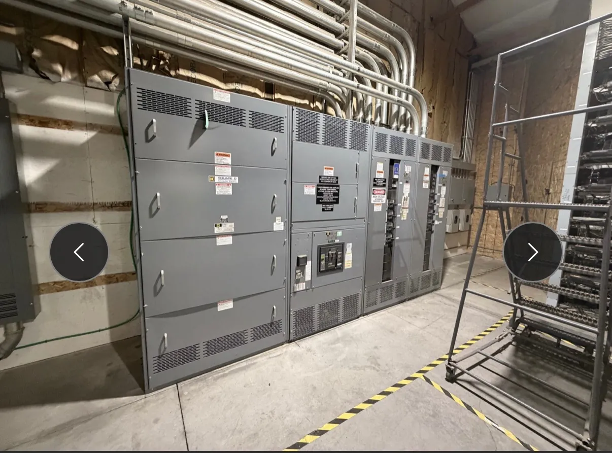
Motor Control Centers for Dayton, Nevada Projects
Motor control centers (MCCs) bring motor starters, protective devices, controls and related equipment together in an organized assembly. For a Dayton facility, the right configuration depends on the motors and driven loads, the electrical system, the building layout and how the equipment will be operated and maintained. A practical design begins with project information—not a general-purpose lineup assumed to fit every site.
We manufacture new custom power-distribution equipment in the USA using all-American components. MCC assemblies can be configured around project requirements, with nationwide shipping that includes Nevada. Short lead times may be supported, but timing depends on the final design, component selection and project schedule; confirm current requirements during quotation.
Motor Starters, VFDs and Control Interfaces
Motor starter selection follows the motor application and its control needs. Across an MCC lineup, units may serve different motors and functions, so the schedule should identify each load, its operating method, control voltage and required interface. Confirm how start and stop commands, status signals, interlocks and alarms connect to the facility’s control system. The project team should also define whether controls are local, remote or coordinated with other equipment.
Where variable-frequency drives (VFDs) are needed, integration requires more than reserving a bucket space. Review drive requirements, motor characteristics, expected operating conditions, heat dissipation, cable routing and the control and communications interfaces. Drives can affect enclosure and lineup arrangements and may require attention to ventilation and separation from other components. A qualified electrical engineer should review the application and any site-specific requirements before the configuration is finalized.
Short-Circuit Ratings and Feeder Protection — Motor Control Centers in Dayton, NV
An MCC short-circuit rating is a withstand or interrupting-related equipment rating, not a statement of system voltage and not a substitute for a project fault-current study. The required rating must be determined for the installation using the available fault current and the protective-device arrangement. Confirm the applicable rating, system voltage, incoming supply details and equipment configuration together; a rating cannot be selected reliably from voltage alone.
Feeder protection should be coordinated with the loads served and upstream and downstream devices. The project team should provide the intended protective-device types and settings, motor data, feeder information and relevant coordination requirements. Changes to devices or lineup arrangements can affect the equipment evaluation and project coordination. Ratings, listings and compatibility therefore require confirmation against the approved design and site conditions.
UL 845 and Applicable Equipment Requirements — Motor Control Centers in Dayton, NV
Ask whether UL 845 is required by the project specification, owner, authority having jurisdiction or other applicable requirements. The answer should be established for the actual MCC and project—not inferred from a general claim about switchgear. Identify the requested listing or evaluation, the scope of the assembly, and any specified construction or documentation requirements early enough to incorporate them into the design review.
Applicable standards and code requirements depend on the equipment and installation. Do not assume that a standard or listing for one product category applies to another, or that a particular assembly carries a listing without confirmation. The project’s qualified electrical engineer and relevant reviewing parties should confirm applicable requirements, system details and approval expectations.
Dayton Site Layout, Cable Entry and Access
Before a lineup is laid out, review the electrical room or outdoor installation area, including available footprint, door and equipment access, cable entry direction and routing space. Top or bottom entry, conduit locations and cable approach can influence section arrangements and terminations. Share drawings or measured site information, including known obstructions and nearby equipment, so the design can be checked against actual installation constraints.
Floor loading and anchoring conditions also warrant review, especially when the building structure or equipment-room floor has defined limits. Confirm available working space and access for installation and future maintenance against applicable project and code requirements. Required clearances are site- and design-dependent; they should be established by qualified project professionals rather than assumed from a standard layout.
Information for a Dayton MCC Quotation
A useful quotation package identifies motor loads and starter or VFD needs, system voltage, available fault-current information, incoming and feeder requirements, control interfaces, requested standards or listing, and preferred lineup arrangement. Include cable-entry preferences, site dimensions, floor-loading information and installation constraints where available. Also describe the desired installation sequence: for example, whether sections must be delivered or positioned in a particular order, and what access is available during placement. These inputs help the manufacturer assess interfaces, configuration and schedule requirements before drawings are developed.
Because Dayton site conditions and project specifications vary, final equipment details must be reviewed with the project’s qualified electrical professionals. We build new custom assemblies in the United States and ship nationwide. Lead time and delivery planning depend on confirmed scope, design decisions and logistics, so discuss the project schedule as part of the quotation review.