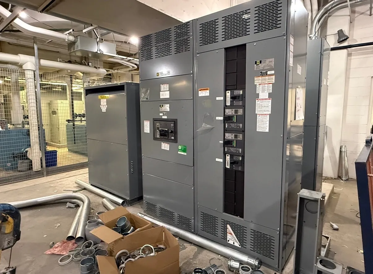
Low-Voltage Switchgear Design for Carson City Projects
Low-voltage switchgear is commonly used where a facility needs to receive and distribute power through a coordinated assembly of protective devices, bus, instrumentation, and associated controls. For a Carson City project, the design begins with the electrical system and the installation—not with a generic equipment configuration. The service arrangement, available fault current, connected loads, operating priorities, and site constraints all influence the appropriate lineup. A manufacturer can build new custom equipment to project requirements, but qualified electrical engineers and the authority having jurisdiction must confirm the design, ratings, and applicable rules.
Power circuit breaker switchgear is often considered when selective coordination, system flexibility, or maintainability is important. The right arrangement depends on how the facility operates and what level of isolation and access its maintenance plan requires. These decisions should be made alongside the one-line diagram and protection study, not inferred from a product name alone.
Compare Breaker Arrangements and Maintainability — Low-Voltage Switchgear in Carson City, NV
Low-voltage power circuit breakers may be arranged as drawout devices, allowing a breaker to be disconnected from the circuit and moved to a designated position for inspection or service. This can support maintenance planning, but it also affects compartment layout, interlocks, access clearances, and the equipment’s overall dimensions. A fixed-breaker arrangement may offer a different balance of footprint, complexity, and service access. Neither approach is automatically best for every Carson City facility.
Consider which devices need independent isolation, whether spare or alternate breakers are part of the operating strategy, and how qualified personnel will access compartments under the facility’s approved procedures. Room dimensions, door and equipment clearances, cable entry, ventilation, and pathways for moving equipment into the electrical room can constrain the choice. Provide room plans and access details early so the lineup can be developed around actual site conditions.
Bus Ratings, System Voltage, and Fault Duty
Bus ratings describe equipment capabilities; they are not the same thing as the system voltage. The project team must identify the intended system voltage and frequency, service configuration, and required continuous-current and short-circuit ratings. The rating basis should be checked against the available fault current at the installation point, upstream protective devices, and the complete power system. Equipment ratings cannot be selected reliably from a building’s nominal voltage alone.
Bus arrangement and material, neutral provisions, grounding, and incoming and outgoing connections also affect the design. A lineup serving several load groups may need sections and devices arranged to match the one-line diagram and planned expansion. Confirm conductor types and sizes, cable or busway interfaces, phase sequence, entry direction, and termination space with the electrical designer. Any rating, configuration, or interface remains subject to engineering review and confirmation for the actual project.
Coordination and Protection Across the System
Protective-device selection should reflect the facility’s fault-current study and coordination objectives. The engineer evaluates how upstream and downstream devices respond to faults, including whether the desired selectivity can be achieved across the operating range. Breaker trip functions and settings, transformer characteristics, conductor limitations, and downstream equipment all matter. A catalog rating or a preliminary device schedule does not establish that a completed system will coordinate as intended.
For Carson City installations, coordination also depends on the actual utility service and the project’s distribution arrangement. Utility information, transformer data, and any service requirements should be obtained through the project’s applicable review process. Changes to the service, transformer, or downstream loads can affect protective-device choices, so the design team should identify assumptions and confirm them before equipment release.
UL 1558, Listings, and Project Documentation
UL 1558 is a standard associated with low-voltage metal-enclosed power circuit breaker switchgear. Whether it applies to a proposed assembly—and whether a particular configuration is listed—must be verified for the specific product and project. Do not assume a standard or listing covers every low-voltage assembly or every combination of devices and options. Applicable standards, markings, and documentation should be confirmed with the manufacturer and reviewed against the project specifications.
Useful quotation inputs include the one-line diagram, equipment schedule, system voltage, bus and short-circuit requirements, breaker quantities and functions, metering and control needs, cable-entry details, room layout, and specified standards. Note unusual environmental conditions, enclosure requirements, access limitations, and future provisions. Clear, coordinated documents help identify design questions before fabrication without presuming approvals or field conditions.
Carson City Permits, Inspections, and Delivery Planning
Permit, inspection, and utility review requirements depend on the installation’s location, scope, service configuration, and the agencies with jurisdiction. The project team should determine which building or electrical permits apply, what plan review and inspection steps are required, and whether the serving utility must review service equipment or connection details. Confirm the responsible authorities and sequence for the specific site; requirements should not be assumed from the city name alone.
New custom switchgear is manufactured in the United States using all-American components and can be shipped nationwide, including to Carson City. Shipping and installation planning still depend on confirmed equipment dimensions, route and receiving access, unloading arrangements, and site readiness. Lead time is project-specific and should be established with the manufacturer after the design scope and required documentation are reviewed.