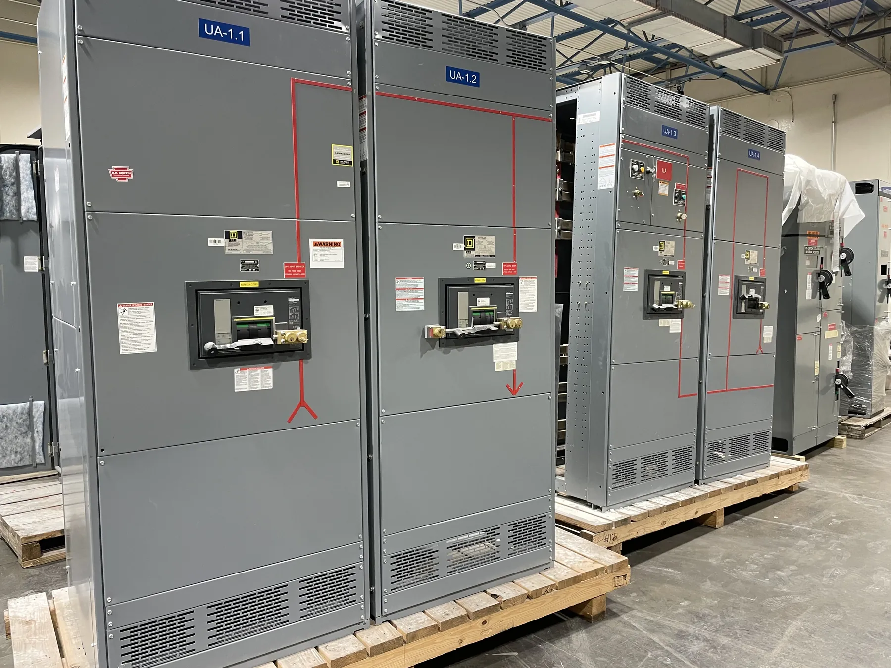
Metal-Clad Switchgear for Carson City, Nevada Projects
Metal-clad switchgear can suit a Carson City facility when the electrical design calls for medium-voltage equipment arranged in enclosed, distinct compartments. The right lineup depends on the system voltage, available fault current, operating scheme, load requirements and installation environment—not on a product name alone. Our U.S.-manufactured equipment is built to order with all-American components and can ship to projects nationwide, including Carson City. Project-specific ratings, construction, listing status and delivery expectations must be confirmed during engineering and quotation.
Carson City site conditions can affect the design and logistics. The installation team should confirm available indoor space, access routes, door and overhead clearances, floor capacity, conduit entry locations and the path for moving sections into position. For outdoor applications, exposure, enclosure requirements and site layout need review as well. These conditions influence lineup arrangement and interfaces; they should be established before the equipment configuration is finalized.
Compartmentalization and Access Design
Metal-clad construction separates functional sections with grounded metal barriers. Depending on the design, compartments may house breakers, bus, instrument transformers and cable terminations. This arrangement helps define boundaries between equipment functions, but it does not eliminate electrical hazards or replace project-specific safety measures. The approved drawings should show the compartment arrangement and how the lineup connects to the rest of the distribution system.
Compartment layout involves practical tradeoffs. Cable entry and termination space must accommodate the specified conductors and bending requirements, while bus connections, control wiring and maintenance access need clear routes. The team should also resolve whether cable access is from the front, rear or both, and how adjacent equipment affects working and removal clearances. A compact footprint may be attractive, but it must not be chosen at the expense of installation access or the manufacturer’s design limits.
Withdrawable Breakers and Operating Scheme
Withdrawable breakers are designed to move among defined positions within their compartments, such as connected, test or disconnected positions, as provided by the equipment design. Their selection affects compartment dimensions, racking interfaces, interlocks, control connections and maintenance planning. Breaker type and ratings must match the switchgear design and the project’s electrical requirements; interchangeability should never be assumed from appearance or a general product description.
Quotation and engineering inputs should identify the intended operating arrangement: incoming sources, feeder circuits, bus sections, tie breakers, metering and any transfer or interlocking functions. The engineer should establish the required switching sequence and control logic. These decisions affect breaker count, lineup sections, auxiliary contacts, control power and external interfaces. Any automatic transfer or remote-control functions also require coordination with the broader control and protection design.
Grounding, Relays and Coordination
Grounding design must be coordinated across the switchgear, incoming source, connected equipment and facility grounding system. The project team should define the grounding method, ground bus connections, cable grounding provisions and any grounding equipment required by the system design. Grounding details depend on the installation and electrical study; they cannot be settled from the city or product category alone.
Protective relays and instrument transformers should be selected around the system study and the required protection functions. Relay settings need coordination with upstream and downstream devices so faults are detected and cleared as intended while maintaining appropriate selectivity. The engineer should review available fault current, transformer and load data, grounding method, source configurations and device characteristics. Changes to system topology or utility source conditions can affect coordination, so the study assumptions should be confirmed before settings and equipment details are released.
IEEE C37.20.2 and Project Requirements
IEEE C37.20.2 is the relevant standard to evaluate when specifying metal-clad switchgear within its scope. The project engineer and manufacturer should confirm the applicable edition, equipment classification and required construction and ratings against the actual specification. A reference to the standard does not, by itself, establish that a particular lineup complies, is listed, or is suitable for every application. Those details require review of the proposed equipment and project documents.
Do not confuse equipment ratings with nominal system voltage. The specification should separately identify the system conditions and the required equipment ratings, including interrupting and withstand requirements where applicable. The engineer must verify that the selected configuration is appropriate for the calculated conditions. Listing or certification requirements, if any, also need to be stated and confirmed for the specific product and scope.
Carson City Permits, Inspection and Utility Review
Before ordering, the project team should determine which authority having jurisdiction reviews the installation at the specific site, what permit applications and electrical plans are required, and which inspections apply. The responsible building or electrical department can confirm current submittal procedures, adopted code requirements, inspection stages and closeout documentation. Requirements may vary with facility type, scope and site jurisdiction, so they should be verified directly rather than inferred from the city name.
If the installation connects to or modifies utility-owned facilities, the serving utility should review the proposed service arrangement and identify its requirements for drawings, protection, metering, equipment interfaces and authorization to connect. Utility review is distinct from permit approval and inspection. For a useful quotation, provide the one-line diagram, system data, load and feeder schedule, fault-current information, relay requirements, environmental and access conditions, applicable specifications, and the status of utility and permitting reviews. Engineering review can then align the equipment proposal with the documented project scope.