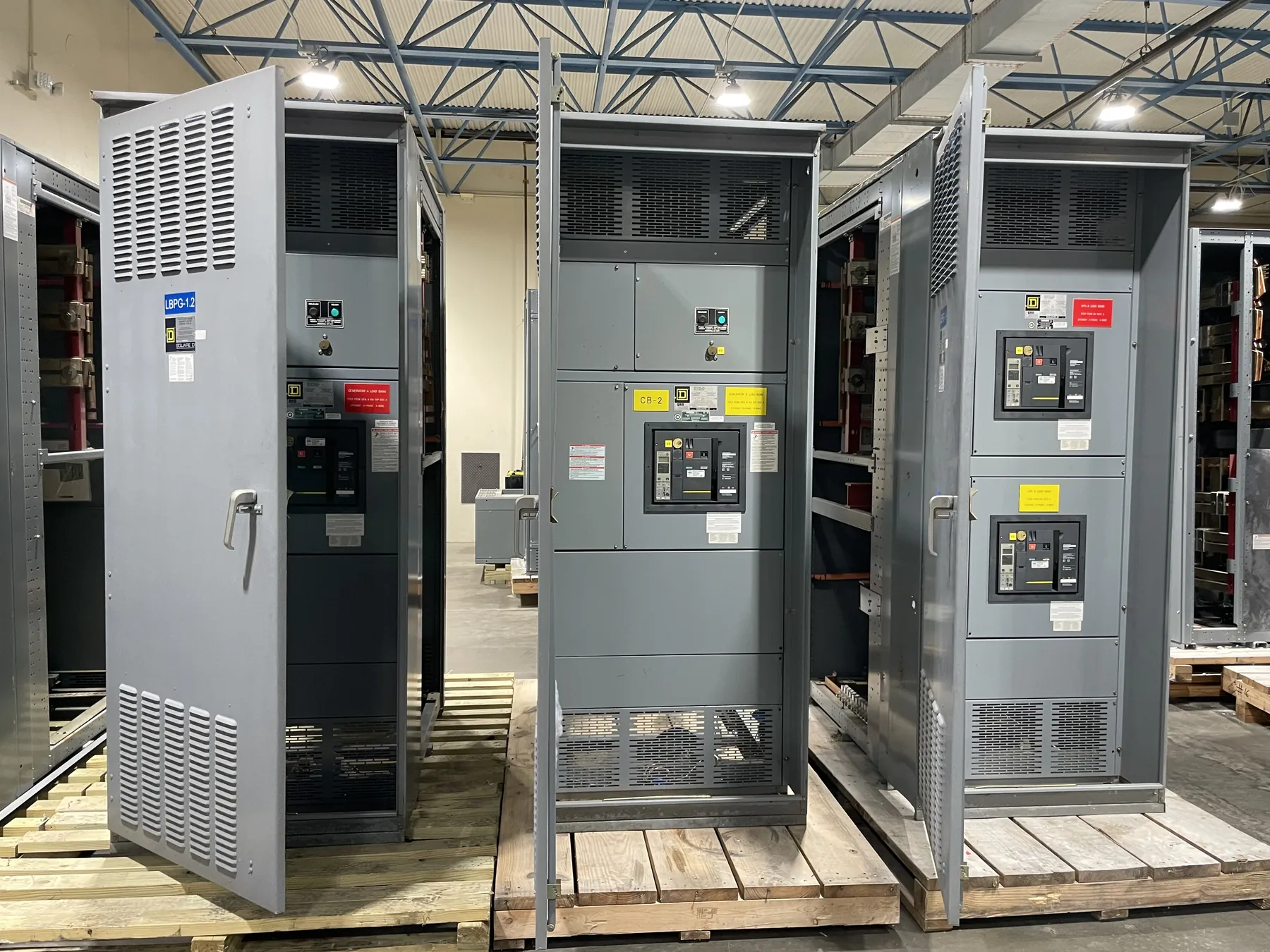
Low-Voltage Switchboards for Boulder City Projects
Low-voltage switchboards bring service and feeder functions together in an assembly selected for a particular building, electrical system and operating plan. For a Boulder City project, the design begins with the source and the loads—not with a standard layout assumed to fit every site. A commercial facility, municipal building, industrial space or other property may have different service interfaces, distribution needs and space constraints. Early coordination among the owner, electrical designer, contractor, utility and equipment manufacturer helps establish those requirements before the switchboard configuration is released.
Our U.S. manufacturing business builds new custom power-distribution equipment using all-American components. Switchboards are manufactured in the United States and can ship nationwide, including to Nevada. A project’s location can affect freight planning, site access and installation sequencing, but it does not determine the electrical design. Equipment ratings, configuration, listing documentation and project-specific details must be confirmed against the approved design and applicable requirements.
Define the Service, Feeder and Utility Interfaces
The service arrangement identifies how power enters the switchboard and how the assembly connects to the rest of the electrical system. Project teams should establish the utility interface, service conductors, metering approach and grounding scheme before releasing the service design. These decisions affect the incoming section, metering provisions, equipment arrangement and coordination with other service equipment. Utility requirements vary, so the serving utility’s applicable criteria should be reviewed rather than inferred from another project.
Feeder arrangements depend on the loads being served, the locations of downstream panels or equipment, and the desired distribution layout. The designer may need to account for feeder quantity, conductor entry and exit, protective devices, future provisions and access for installation and maintenance. Changes to feeder locations or section arrangements can influence enclosure dimensions and connection details. Drawings that show the intended circuit destinations and physical routing help the manufacturer prepare a configuration that aligns with the project rather than relying on assumptions.
Coordinate Bus Sizing and Available Fault Current
Bus sizing is a design decision based on the electrical design, specified ratings and the conditions for which the assembly is intended. It should not be selected by considering a single load figure in isolation. The engineer must evaluate the service and feeder requirements, expected operating conditions, conductor interfaces and applicable design criteria. A switchboard’s current rating is not the same thing as the system voltage, and neither value alone establishes whether an assembly is suitable for a particular installation.
Available fault current at the switchboard location is another essential input. It affects the required short-circuit rating and coordination with upstream protective devices and downstream equipment. The project team should provide the available-fault-current information used for design and identify the source and assumptions behind it. If the source configuration, transformer information or upstream protection changes, the design basis may need review. The equipment rating must be evaluated for the actual system and installation; it cannot be determined from the city name or a general product description.
Understand Where UL 891 May Apply
UL 891 applies to applicable low-voltage switchboards, but that does not mean every switchboard configuration or all power-distribution equipment is covered by that standard. Project specifications should identify the required product category and documentation, and the proposed assembly must be evaluated against the project’s requirements. Do not assume that a reference to UL 891 establishes a listing for a particular configuration, or that it applies to equipment outside its scope.
Before procurement, request and review project-specific listing documentation for the equipment being offered. Confirm that the documentation corresponds to the proposed assembly and its intended application. Ratings, listing status and construction details require confirmation; they should not be inferred from a general statement about a product family. The electrical designer and other responsible project professionals should resolve specification questions before the equipment is released for manufacture.
Prepare a Complete Boulder City RFQ
A useful request for quotation gives the manufacturer enough information to develop a project-specific proposal. Include the electrical one-line diagram, project specifications, service characteristics, required current and voltage ratings, available fault current, protective-device requirements, metering needs, grounding approach and feeder schedule. Identify enclosure requirements, cable-entry preferences, physical limitations and any project-specific documentation or listing requirements. If drawings are preliminary, mark them clearly and identify open decisions that may affect the design.
For a Boulder City site, also share practical delivery and installation constraints where known, such as access limitations, receiving arrangements, site schedule and space available for equipment placement. These details help with configuration and freight planning without substituting for electrical engineering review. A complete, coordinated RFQ makes it easier to identify assumptions, clarify interfaces and compare proposals on a consistent basis.
Coordinate Design Release and Delivery
Before release, the project team should reconcile the switchboard drawings with the latest one-line diagram, utility interface, metering requirements, grounding scheme, feeder destinations and approved ratings. Changes made after design review can affect equipment layout and connections, so unresolved items should be documented and assigned for confirmation. Coordination with upstream and downstream equipment is also important: protection, physical interfaces and installation details need to work together across the complete distribution system.
Custom low-voltage switchboards are manufactured to the agreed project requirements, with short lead times supported where the design and production schedule allow; no exact lead time is assumed. Nationwide shipping supports projects in Boulder City, while delivery timing and site handling depend on confirmed project details. The final equipment selection and installation design remain subject to qualified engineering review, utility coordination and applicable project requirements.