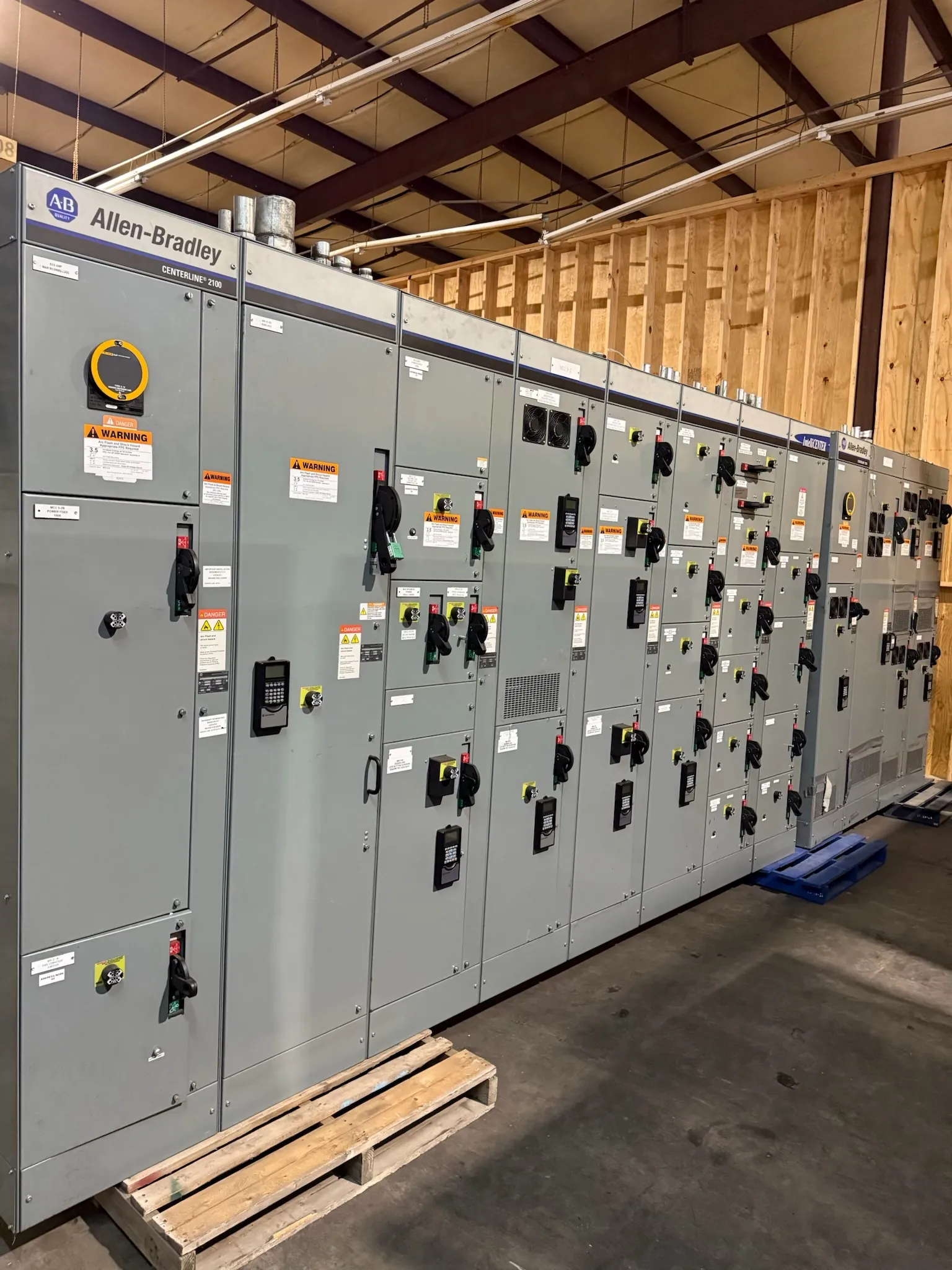
Medium-Voltage Switchgear for Boulder City Projects
Medium-voltage switchgear is selected around the electrical system it must serve, not by a product name alone. For a Boulder City project, the design team should establish the system voltage class, available fault duty, insulation requirements, protective scheme and cable arrangement before requesting a final configuration. Those decisions affect the equipment lineup, compartments, bus design, terminations and interfaces with upstream and downstream systems. Our U.S.-built assemblies use all-American components, and we manufacture new custom power-distribution equipment for shipment to Nevada and nationwide. Final equipment details depend on project documents and engineering review.
Set the Voltage Class and Fault-Duty Basis
System voltage and equipment ratings are related but are not interchangeable. Project documents should identify the nominal system voltage and require the engineer to confirm the appropriate maximum equipment voltage and insulation level. The available fault current at the switchgear location also matters: the gear’s short-circuit and momentary capabilities must be suitable for the study results and expected system conditions. A rating cannot be chosen reliably from a facility’s service voltage alone. Utility data, transformer information, upstream protective devices and any planned sources such as generators can affect the fault-duty basis. The responsible engineer must confirm the design values and whether system changes require a revised study.
Choose a Configuration That Fits the Protection Scheme
Feeder and incoming-section arrangements should follow the one-line diagram and the functions each circuit must perform. The specification may call for circuit breakers, fused devices or other switching arrangements, depending on the application and the protection philosophy. Protective relays are selected and configured to suit the system, instrument transformers, trip logic, communications needs and coordination study. Relay functions, settings and interfaces should not be inferred from a generic equipment description. The engineering team should define required protection, control power, alarms and interlocks, then confirm that the proposed lineup can accommodate them. Selectivity with upstream and downstream devices must be evaluated against the complete system, not assumed from component ratings.
Plan Cable Terminations, Grounding and Metering Early
Cable entry direction, conductor type, termination space, phase arrangement and access clearances can shape the enclosure and lineup layout. The cable specification should identify conductor size and construction, termination requirements and routing constraints; actual fit and compatibility must be confirmed for the selected equipment. The grounding scheme also needs deliberate definition, including how the switchgear bonds to the facility grounding system and how system grounding is established. For a Boulder City service, the utility interface and metering arrangement should be resolved with the utility and project engineer before service design is released. Metering location, instrument-transformer requirements, ownership boundaries and grounding details can affect both the equipment and the service design. Utility requirements are project-specific and require direct confirmation.
Account for Boulder City Site and Delivery Conditions
Site conditions can influence the enclosure, access plan and installation sequence. The project team should provide indoor or outdoor location, environmental exposure, elevation information when required by the equipment specification, room dimensions, door and aisle clearances, cable routes and lifting or placement constraints. Boulder City delivery planning should also account for the receiving location, unloading arrangements, site access and coordination with construction schedules. These are planning inputs, not a promise of a particular delivery date. Short lead times may be supported by the manufacturing process, but timing depends on an approved scope, component requirements and production scheduling. Confirm the required schedule and shipping details when requesting a quotation.
Provide the Information Needed for a Useful Quote
A quotation can be more accurate when the request includes the one-line diagram, load and feeder information, system voltage, fault-current data, protection requirements, cable details, metering and grounding criteria, environmental conditions, and applicable project specifications. Include the required number and type of sections, preferred lineup arrangement, control and communications needs, and any interface requirements from the utility or other equipment suppliers. Clearly identify which values are preliminary and which have been approved by the responsible engineer. Missing or conflicting inputs may require clarification before the design and price can be finalized.
Confirm Ratings and Project Details Before Release
Medium-voltage equipment ratings, insulation levels, protective-device selections and available configurations must be checked against the project’s engineering documents and site conditions. Applicable standards and any requested listing or certification should be identified for the specific equipment and scope; UL 891 applies to applicable low-voltage switchboards and should not be represented as a medium-voltage switchgear standard. Before release, the project engineer should review the proposed design, utility interface, metering, grounding, protection coordination, terminations and installation requirements. That review helps ensure the manufactured lineup reflects the actual Boulder City project rather than assumptions based on a general description.