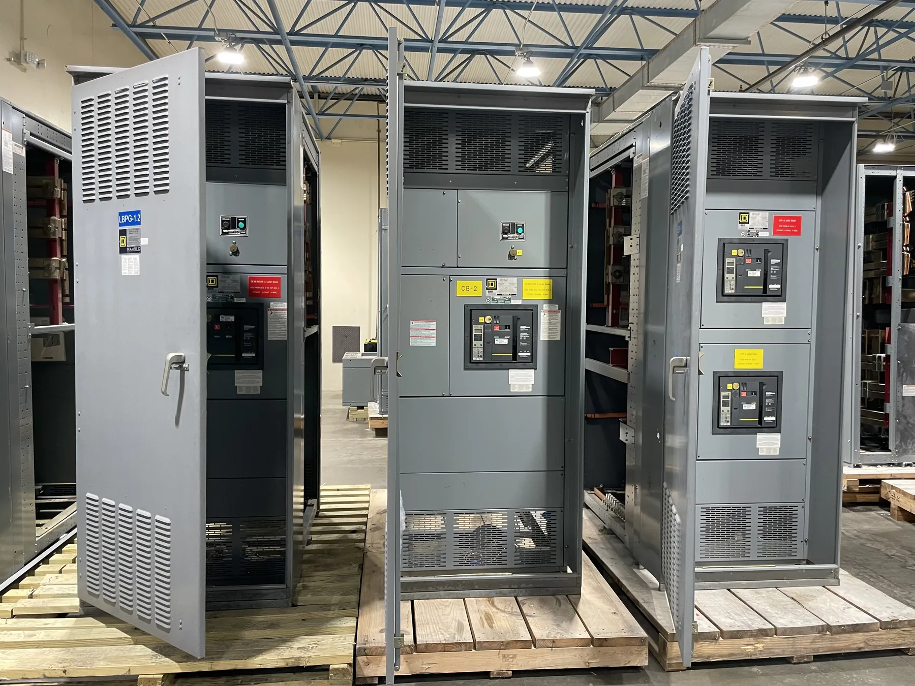
Planning Switchgear for a Boulder City Project
For a commercial, institutional, industrial, or infrastructure project in Boulder City, specify distribution equipment around the actual service arrangement and facility loads—not just a nominal voltage or a preferred lineup format. The design team should establish where utility responsibility ends, where customer equipment begins, and which components the project needs at that interface. Those decisions shape the switchgear configuration, metering provisions, protective devices, physical layout, and information required for a firm equipment quotation.
Equipment can be manufactured in the United States and shipped to Nevada; no local manufacturing facility is implied. Delivery planning should account for the project’s receiving location, access route, unloading method, indoor or outdoor staging conditions, and the sequence for moving sections into the electrical room. Confirm doorway and corridor clearances, floor and housekeeping-pad details, available laydown space, and whether the lineup must arrive in sections. These conditions can affect enclosure and section arrangements, shipping configuration, and installation coordination.
Define the Utility Interface Before Releasing Service Design
Start with the serving utility’s current service requirements and the project’s approved electrical design. Identify the service characteristics, point of connection, ownership boundary, available fault-current information, and any required disconnecting or protective functions. Do not infer these details from a nearby building or an older project: utility requirements and site conditions must be confirmed for the specific service.
Document which equipment is utility-owned and which is customer-owned, along with the physical and electrical interface between them. The interface may affect incoming conductors, termination space, compartment arrangement, access, and the location of service disconnects. If the service design or utility review is not complete, identify the open items rather than treating preliminary assumptions as final. The project engineer and utility should resolve applicable requirements before manufacturing details are released.
Coordinate Metering, Grounding, and Protection
Metering is more than reserving a cabinet space. Clarify whether metering is provided by the utility or the customer, where it is located, what instrument transformers or provisions are required, and which party supplies and installs associated components. Confirm the utility’s metering standards and access expectations. Metering requirements can influence lineup dimensions, barriers, wiring space, and coordination with the service entrance equipment.
Define the grounding and bonding scheme with the electrical engineer, including the service configuration and the intended treatment of neutral and equipment-grounding conductors. These details affect bus arrangements, terminations, bonding provisions, and coordination with downstream distribution. Protective-device selections and settings also require engineering review of the system and its available fault current. A manufacturer should not determine the site’s grounding design, protection strategy, or arc-flash conclusions from a product description alone.
Choose Ratings and Construction for the Actual System
Specify the system voltage separately from equipment ratings. In particular, a voltage designation is not a substitute for confirming the required continuous-current rating, short-circuit withstand or interrupting rating as applicable, and the ratings of individual devices. The design professional must establish the required values from the service information and system study. Confirm that the selected equipment and every relevant component are suitable for the application; do not assume one rating applies to the entire assembly.
For low-voltage switchboards, UL 891 may be relevant when the project calls for equipment within that standard’s scope. It does not establish coverage for every kind of switchgear or for medium- or high-voltage equipment. Listing status, applicable standards, construction details, and project requirements need confirmation for the specific proposed product. Other practical choices include incoming and outgoing section arrangement, breaker or switch types, feeder count, cable entry direction, enclosure conditions, future provisions, and space for field terminations.
Prepare Complete Quotation and Submittal Inputs
A useful request for quotation includes the one-line diagram, equipment schedule, service and system data, load or feeder requirements, metering requirements, grounding scheme, and specified ratings. Include available-fault-current or study information when established, as well as applicable utility documents and project specifications. Drawings should show room dimensions, access constraints, cable routing assumptions, and required equipment interfaces. Clearly mark unresolved items so engineering review can identify decisions needed before release.
Also state the number and type of sections, requested accessories, control or indication requirements, enclosure environment, and project submittal expectations. Identify the required documentation and review milestones without assuming that a quotation confirms design approval or utility acceptance. A manufacturer can use these inputs to develop a configuration and identify exceptions or clarifications; the engineer of record and relevant authorities remain responsible for project design and approvals.
Plan Manufacturing, Shipment, and Site Coordination
Once the configuration and technical requirements are reviewed, custom equipment can proceed through drawings, customer review, manufacturing, and shipment planning. Short lead times may be supported, but timing depends on the approved design, component requirements, drawing decisions, and production scheduling; confirm the project’s current schedule during quotation and order review. U.S.-built assemblies using all-American components can ship nationwide, including to Boulder City, subject to the confirmed equipment configuration and shipment plan.
Before shipment, coordinate the receiving contact, delivery access, unloading responsibility, storage conditions, and installation sequence with the project team. Nevada site conditions can vary, so verify the actual indoor or outdoor environment, dust exposure, temperature considerations, and protection needed during construction with qualified project personnel. Final dimensions, ratings, listings, utility interface, and other design details require confirmation through engineering review and site-specific coordination.