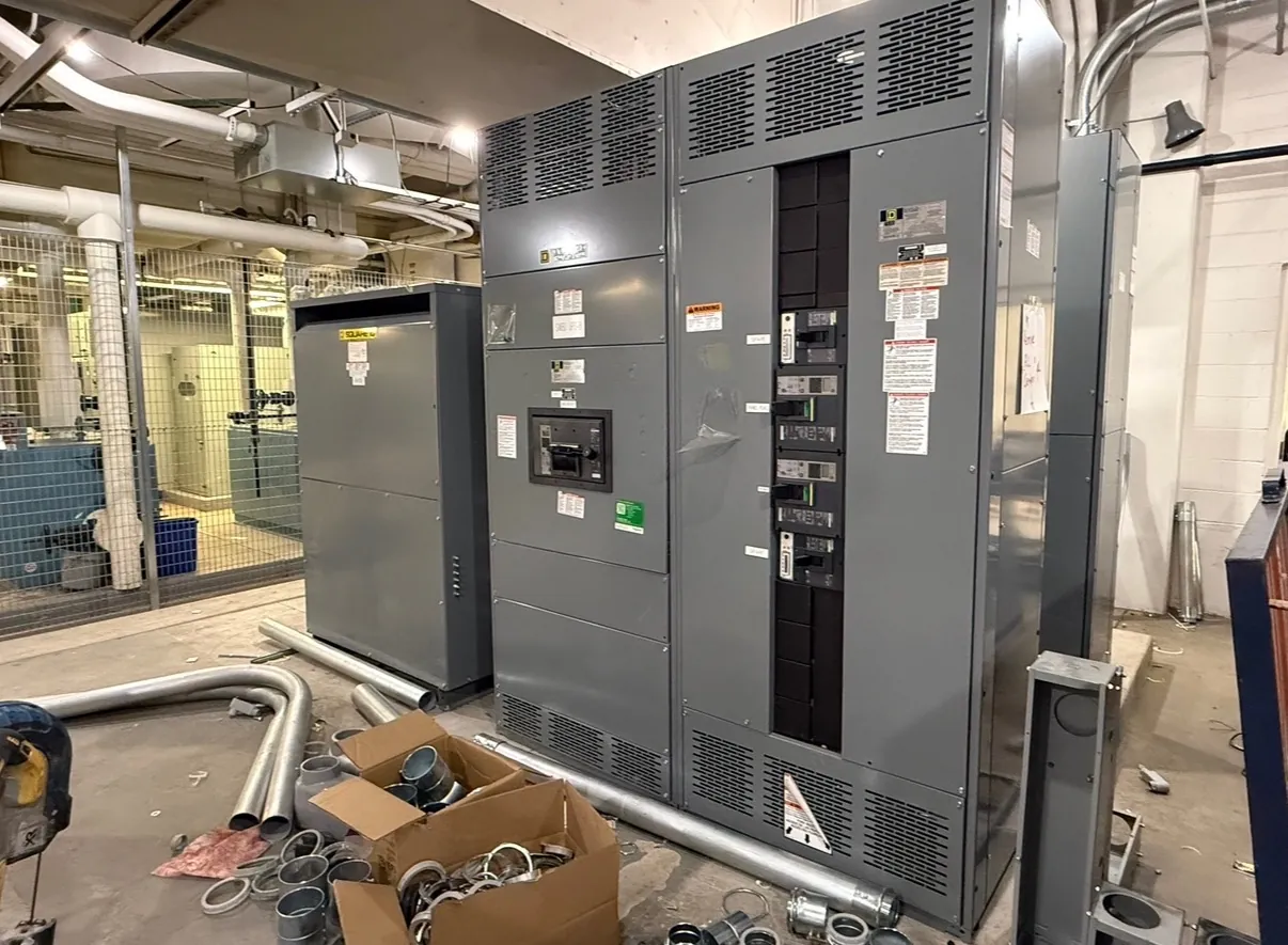
Start With the Distribution System
A useful switchgear plan begins with a clear picture of how power enters a Nevada facility and where it must go. Gather the current one-line diagram, equipment schedules and expected operating modes. Identify utility and on-site sources, transformers, major loads and any connections to existing distribution. A qualified electrical engineer should check that these documents describe the actual project rather than an assumed standard arrangement.
Our planning resources explain the choices behind new U.S.-manufactured electrical distribution equipment built with all-American components. They are starting points for discussions, not substitutes for a design. Use them to organize unanswered questions about ratings, physical interfaces and responsibility, then reconcile the answers with the project specification and the information supplied by the utility.
Use Voltage Guidance to Identify the Right Equipment Class
Record nominal system voltage, phase and wire configuration, grounding method and whether a neutral is needed. Equipment rated maximum voltage and insulation requirements must suit the system; a familiar voltage label alone does not establish the necessary equipment class. Different sources or transformers may create several voltage levels on the same site, each requiring its own review.
Voltage guides can clarify line-to-line and line-to-neutral terminology and help distinguish low-voltage distribution from medium-voltage equipment. They also highlight the need to check cable terminations, protection and applicable product standards. Ask the engineer to verify system details and utility requirements before a voltage description becomes a manufacturing specification.
Translate Loads Into Current and Fault Requirements
Ampacity guidance helps connect calculated demand, continuous loading, ambient conditions and expansion plans to the ratings of the main bus and feeder devices. Keep connected load and calculated demand distinct: simply adding nameplate values may not represent simultaneous operation. Identify spare capacity intentionally instead of assuming unused physical space supplies additional electrical capacity.
Short-circuit guidance addresses a different question: whether equipment and protective devices are suitable for the available fault current at their location. Obtain the utility contribution and consider other sources, including motors or generation where applicable. A coordination study can evaluate device operation across relevant fault levels and operating modes; a bus current rating does not replace that study.
Plan the Equipment Room and Interfaces
Enclosure resources cover the conditions that surround the equipment: indoor or outdoor placement, moisture, dust, temperature, ventilation and access. Record the actual site conditions and any specified enclosure rating. Verify required working clearances and exit routes with the responsible engineer and applicable authorities, rather than assuming the lineup footprint represents the entire space required.
Show incoming and outgoing cable routes, conduit entry, nearby equipment and handling restrictions on a layout. Note whether a generator, transfer switch, metering system or building controls must connect to the assembly. Interface details influence section arrangement, wiring and the information needed by the people preparing drawings and installing the equipment.
Use the FAQ and Glossary to Resolve Ambiguity
The frequently asked questions resource addresses equipment types, documentation, testing and the division between manufacturing and field work. It can help a project team decide which questions to ask when reviewing a proposal or considering new equipment for an existing system. Answers remain general until the project voltage, ratings, site conditions and responsibilities are known.
The glossary explains terms such as bus ampacity, interrupting rating, short-circuit current and selective coordination. These terms describe related but different properties. Consult the definitions when a drawing, specification and equipment schedule use inconsistent wording, then ask the engineer or manufacturer to clarify the exact requirement rather than relying on informal terminology.
Carry the Research Into Project Review
For a project-specific quotation, assemble the one-line, equipment type and quantities, voltage, bus current, available fault current, enclosure needs, feeder schedule and requested delivery location. Include a preliminary schedule and identify which information is still being developed. The manufacturing scope and any requested factory tests should be described separately from installation and commissioning work.
During submittal review, compare the proposed equipment, ratings, interfaces, applicable standards and any requested listing documentation with the approved design. Confirm who will resolve deviations and approve changes before manufacture. Final acceptance and energization remain subject to the project’s qualified professionals, utility and authorities having jurisdiction, as applicable.