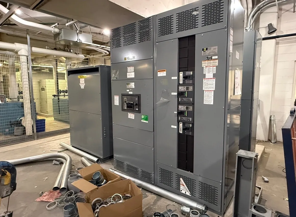
Drawout breaker definition for switchgear users
A drawout breaker is a circuit breaker mounted in a removable assembly, often called a cassette, cradle or compartment, that lets the breaker move among defined positions within compatible switchgear. Its purpose is to make the breaker removable for inspection, maintenance or replacement without dismantling the entire lineup. “Drawout” describes the mounting and connection arrangement; it does not, by itself, specify the breaker’s interrupting capability, voltage class, control features or suitability for a particular system.
The exact arrangement depends on the equipment design. Some low-voltage switchgear uses drawout breakers, while other assemblies use fixed-mounted breakers. Medium-voltage equipment may also have removable breaker designs, but its construction and operating requirements differ. The equipment drawings and manufacturer documentation—not the term alone—identify what can be withdrawn, how it interfaces with the compartment and which positions are provided.
Connected, test and disconnected positions — Drawout Breaker Definition
Where the design provides them, connected, test and disconnected are distinct breaker positions. In the connected position, the breaker’s primary power contacts engage the switchgear’s corresponding contacts. The control circuit may also be connected, allowing the breaker’s electrical operation and status functions to work as designed. The breaker’s rating and the compartment’s configuration must be compatible for this position to be valid.
In a test position, primary power contacts are separated, while specified control connections may remain engaged. That arrangement can support functional checks of controls or electrical accessories without making the same primary power connection as the connected position. The word “test” does not mean that every function is available, that the compartment is inherently safe, or that a particular test is permitted. Which circuits remain connected is design-specific.
In the disconnected position, the breaker is separated from its normal primary and, depending on the design, control connections. Some equipment also has a separate withdrawn or removed condition. These terms are not interchangeable across all manufacturers. A position indicator, interlock and physical arrangement must be interpreted using the applicable equipment documentation and approved site procedures.
How it differs from related terms
A fixed breaker is attached in place rather than routinely moved between defined positions within a compartment. A drawout breaker is not simply a portable breaker: it must be designed for its particular cradle, contact arrangement, mechanical guides, interlocks and control connections. A breaker that appears to fit is not necessarily electrically or mechanically compatible.
“Withdrawable” may describe equipment that can be removed, while “drawout” often refers to a specific arrangement with guided movement and designated positions. Usage varies, so project documents should state the intended construction and position functions rather than rely on terminology alone. A switchboard is an assembly; a breaker is one component within it. For applicable low-voltage switchboards, UL 891 may be relevant, but that standard should not be assumed to cover every switchgear product or voltage class.
Design choices and equipment interfaces
Choosing a drawout arrangement involves more than deciding whether a breaker should be removable. Engineers consider the system voltage, continuous-current and interrupting ratings, available fault current, protective-device coordination, bus arrangement, enclosure and compartment dimensions, control voltage, trip unit functions, auxiliary contacts and communications needs. Ratings must be checked against the application; a breaker’s rating is not the same thing as the system voltage.
Drawout construction can make planned access to a breaker more practical, but it adds interfaces and mechanisms that require compatible design and maintenance. Contact geometry, alignment, shutters where provided, position indication and interlocks must work together. Space for equipment access, cable entry, ventilation and future service also matters. A fixed arrangement may be preferable in some applications, depending on facility requirements, equipment configuration and maintenance strategy.
Operational limits and coordination
Position names do not replace a complete understanding of the assembly. Interlocks, racking mechanisms and electrical controls vary by manufacturer and model. They are intended to function as part of a specified design, but they should not be treated as proof that an action is safe under every condition. Operating, inspection and testing tasks require qualified personnel, the correct equipment documentation and site-specific procedures. This definition is not a procedure for moving or servicing an energized breaker.
Protection must also be considered at the system level. A breaker’s trip settings and time-current behavior affect coordination with upstream and downstream devices, and the available fault current influences equipment selection. Changes to breaker type, trip unit or settings can alter the study assumptions. Qualified electrical engineers should review the one-line diagram, fault-current information and coordination requirements for the actual installation.
Information to specify for a drawout breaker
For a new custom switchgear quotation, provide the one-line diagram and available project specifications, including system voltage, required breaker ratings, fault-current data, bus and feeder arrangement, control-power details, protection functions, accessory requirements and any specified positions. Identify the applicable equipment standard or listing requirement and whether the project calls for a low-voltage switchboard or another equipment category. Ratings, listings and interfaces require confirmation against the proposed design.
A U.S. manufacturer of new custom power-distribution equipment can review these inputs with the project team before finalizing a configuration. Assemblies made with all-American components, built in the USA and shipped nationwide can support projects in Nevada as well as elsewhere, but facility access, room dimensions, environmental conditions, receiving arrangements and schedule constraints should be documented early. Final design suitability depends on engineering review of the equipment and the installation.