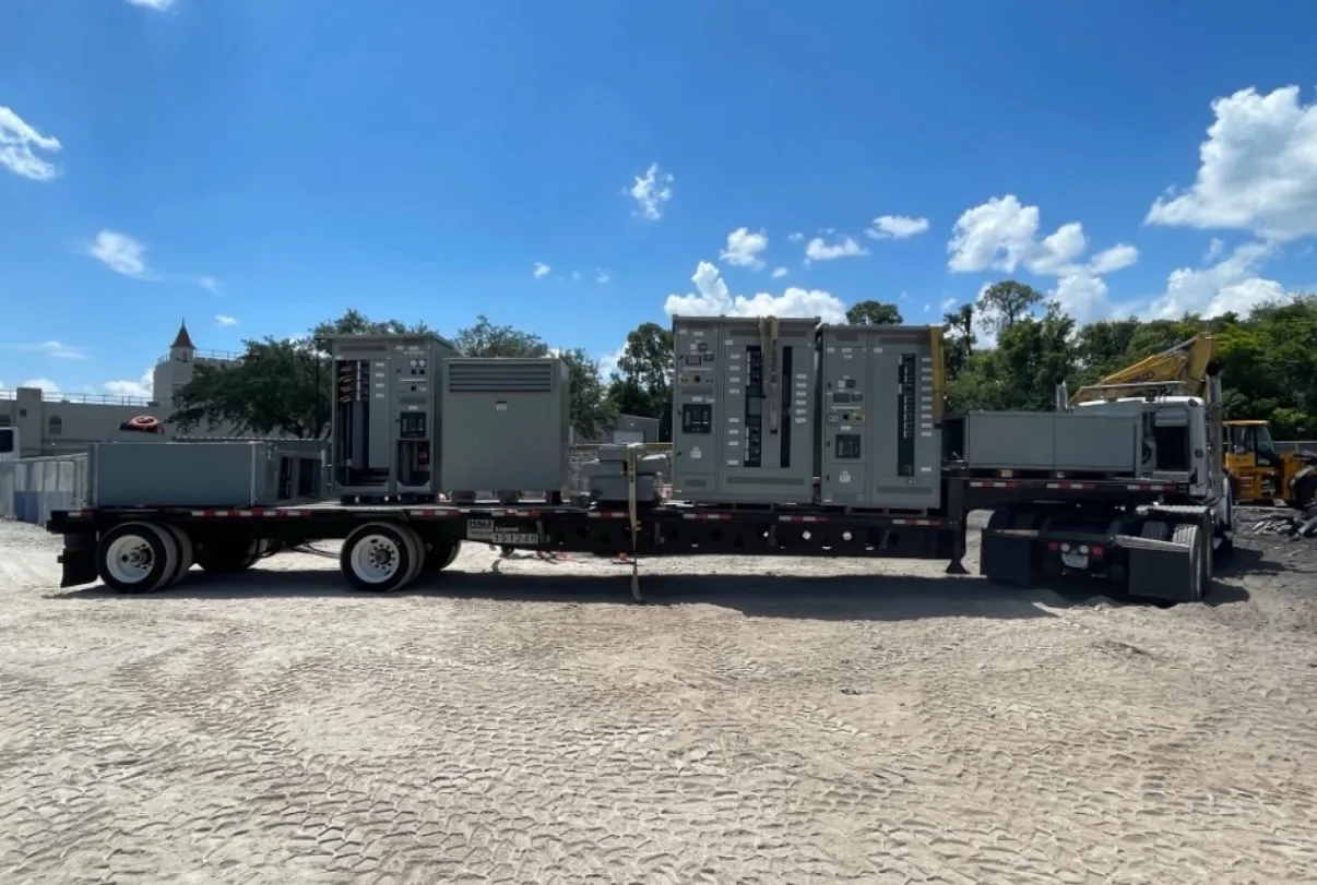
Planning 277/480 V Switchgear and Distribution
A 277/480 V system supplies two useful voltage levels from a four-wire, three-phase arrangement: 480 V line to line and 277 V line to neutral. That combination can serve three-phase motors and other 480 V loads alongside compatible 277 V lighting circuits. For facility owners, contractors, and electrical engineers, the key is to specify the actual system and load requirements—not to treat “277/480 V” as a complete equipment specification. Switchboard configuration, ratings, protective devices, conductor and neutral arrangements, and connections to upstream and downstream equipment all require project-specific review.
Custom switchgear and distribution equipment can be manufactured in the USA with all-American components and shipped to Nevada. Early coordination helps align the equipment design with the site’s electrical documents and installation constraints while supporting a short-lead-time manufacturing approach. Schedule and shipping details depend on the confirmed scope; they should be established during quotation and project planning rather than assumed from the nominal voltage.
Line-to-Line and Line-to-Neutral Loads
At this system voltage, 480 V line-to-line circuits are commonly considered for three-phase motors and other equipment designed for that supply. A 277 V line-to-neutral circuit may serve lighting or other loads specifically rated for 277 V. These are different circuit connections, not interchangeable ways to power any load. Equipment nameplates and manufacturer documentation should establish the required voltage, phase, frequency, and connection before circuit assignment.
Load distribution across phases matters. A panel or distribution section should reflect the expected mix of 480 V three-phase loads and 277 V line-to-neutral circuits, including anticipated additions where the project design accounts for them. Uneven phase loading can affect current distribution and neutral current. The designer should use the actual load schedule and operating assumptions to determine how circuits are arranged and whether the proposed distribution equipment fits the intended use.
Neutral Sizing and Load Characteristics
The neutral is a functional current-carrying conductor for line-to-neutral loads; it should not be treated as optional simply because many major loads are three-phase. Its required arrangement and sizing depend on the connected loads, their characteristics, applicable design requirements, and the equipment configuration. Lighting and electronic loads may have current characteristics that make a simple assumption about neutral loading unsuitable. A qualified electrical engineer should evaluate the load mix and specify neutral requirements for the complete system.
Quotation documents should identify whether a neutral is required in each relevant section and provide the design basis where available. They should also clarify grounding and bonding interfaces and identify any special equipment connections. Final conductor and bus details require engineering review against the project drawings, applicable code requirements, and site conditions; voltage alone does not determine them.
Motor and Lighting Feeder Decisions
Motor feeders and lighting feeders can impose different demands on a 277/480 V distribution lineup. For motor circuits, provide the motor voltage and phase, load information, starting or control requirements, and the intended protective-device arrangement. Starting characteristics and coordination with downstream motor controls may influence feeder selection. The switchgear design should be checked against the motor-control equipment and the project’s protection scheme rather than selected solely from a motor’s nominal voltage.
For 277 V lighting, identify the number and distribution of circuits, connected load information, control interfaces, and any project-specific requirements. Lighting schedules may change during design, so the engineer should confirm the final circuit allocation and protective-device needs. Where both lighting and motor loads share distribution equipment, the panel or switchboard layout should make their feeder interfaces clear and support the intended maintenance and expansion plan.
Service Ratings and Protective Coordination
System voltage and equipment ratings describe different things. The stated 277/480 V identifies the system voltage arrangement; it does not establish the required current rating, interrupting rating, short-circuit withstand capability, or protective-device settings. Those selections depend on the available fault-current information, upstream protection, conductor and load data, and downstream equipment. Ratings and any applicable product listings must be confirmed for the specific assembly and project. UL 891 applies to applicable low-voltage switchboards; it should not be assumed to cover every switchgear product or configuration.
Coordination at the service voltage involves reviewing protective devices across the distribution path, including upstream service equipment and downstream feeders or motor-control equipment. The engineer needs reliable source and fault-current data, device information, and the intended coordination objectives. Selective coordination, where required by the project, must be evaluated for the actual devices and system—not promised from a voltage designation. Changes to the source, transformer, or feeder design can affect the review and should be communicated before equipment details are finalized.
Information for a Project-Specific Quotation — 277/480 V Switchgear and Distribution
To develop a useful quotation, provide the one-line diagram, equipment location and installation constraints, system voltage and phase, available service data, load schedules, and required feeder and neutral arrangements. Include protective-device preferences or specifications, relevant downstream interfaces, enclosure and access requirements, and the applicable project documents. Note any known site limitations that may affect shipping, handling, or placement in a Nevada facility; these conditions can influence equipment dimensions and delivery planning without changing the need for engineering confirmation.
Manufacturer engineering and the project’s qualified electrical professionals should resolve open design questions before release for production. A custom assembly can be tailored to documented requirements, but the final ratings, listing applicability, coordination, and installation details depend on that review. Clear inputs help the manufacturer build new equipment suited to the project and support a coordinated path from design documents through nationwide shipment.