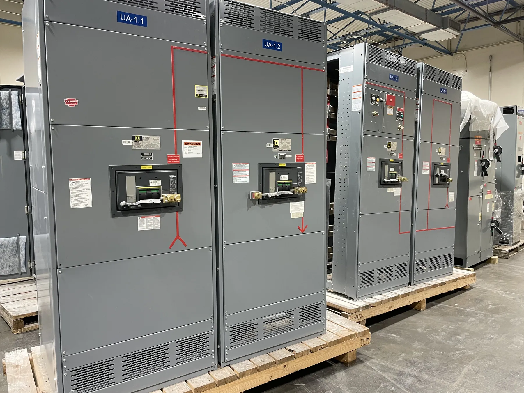
Choosing 15 kV Class Equipment for a Medium-Voltage System
“15 kV Class” identifies an equipment voltage class; it does not mean the switchgear operates at exactly 15 kV. The applicable system voltage, grounding arrangement and equipment ratings must be established for the installation. A nominal system voltage alone is not enough to select a lineup: the engineer also needs to consider maximum system voltage, insulation requirements, fault exposure, connected loads and the electrical interface with upstream and downstream equipment.
For a Nevada facility, selection should reflect the actual distribution arrangement and site conditions, not just a voltage label on a drawing. A plant expansion, utility service, campus feeder or large building distribution project may impose different requirements for incoming connections, feeder count, metering, protection and future capacity. A 15 kV Class design should be developed against the project’s electrical documents and reviewed by qualified engineers familiar with the installation.
Insulation Level and System Interfaces
Insulation selection concerns the equipment’s ability to withstand applicable operating and transient voltages. It is related to, but distinct from, the nominal system voltage and the equipment’s short-circuit rating. The required insulation level depends on the system and project conditions, including grounding, exposure to switching or lightning surges, and the interfaces to cables, transformers and other apparatus. Those details should be resolved in the design rather than inferred from the 15 kV Class designation.
Connection details can shape the equipment layout. Identify cable entry direction, termination type, conductor arrangement, phase orientation, grounding provisions and clearances at each interface. Confirm whether the lineup connects to a transformer, overhead-to-cable transition, existing switchgear or another manufacturer’s equipment. Physical and electrical compatibility both matter; matching voltage classes by themselves does not establish that two assemblies can be connected as intended.
Short-Circuit Duty and Protective Relaying
Short-circuit duty is a system-specific design input. Available fault current, clearing time, equipment withstand requirements and the behavior of upstream sources all influence the appropriate ratings and protection scheme. A rating must be checked against the project’s calculated conditions and the applicable equipment documentation; it should not be assumed from nominal voltage or from another installation’s design.
Protection choices may include feeder overcurrent functions, transformer protection, bus protection or other functions appropriate to the system. The required relays, instrument transformers, trip devices, control power and communications depend on the one-line diagram and the protection philosophy. Coordination studies should account for upstream and downstream devices, transformer characteristics, conductor limits and the consequences of faults on critical loads. Relay settings and operating logic require qualified engineering review and commissioning for the actual system.
Lineup Configuration, Access and Facility Conditions
Panel arrangement should support the intended sequence of incoming, bus, feeder and metering sections while accommodating the room and cable routes. Provide project drawings showing available floor space, doors, overhead constraints, cable trenches or conduits, wall conditions and the planned path for moving equipment into the electrical room. These constraints can affect section dimensions, access surfaces, cable termination space and whether the proposed arrangement is practical to install and maintain.
Maintenance access is a design consideration, not an afterthought. Review required working space, door and panel clearances, cable access, removable components, ventilation and the facility’s maintenance plan. Environmental conditions such as dust, moisture, altitude, temperature range and corrosive exposure may affect enclosure and component selection. Nevada sites vary considerably in elevation, climate and building conditions, so site-specific information is more useful than a statewide assumption.
Information Needed for a 15 kV Class Quotation
A useful quotation package typically includes the one-line diagram, equipment schedule, system voltage and grounding method, available fault-current information, protection requirements, cable and termination details, and the desired lineup arrangement. Include specified insulation and short-circuit ratings, metering needs, control power, communications, enclosure requirements, and any applicable project standards. Identify adjacent equipment and explain which interfaces are existing and which are part of the new scope.
Also provide the electrical-room layout, access route and relevant environmental conditions. If some information is still being developed, identify it as pending instead of treating an assumption as a confirmed requirement. Ratings, listings and project-specific details require confirmation during engineering review. UL 891 applies to applicable low-voltage switchboards; it should not be treated as a listing basis for medium-voltage 15 kV Class switchgear.
Engineering Review and Manufacturing Coordination
Once requirements are defined, the proposed configuration can be checked against the system interfaces, ratings, protection scheme and physical constraints. Changes to fault-current assumptions, cable entry, relay functions or room dimensions can affect the design and should be reviewed before release. Final equipment selection depends on qualified engineering and project documentation, not on voltage class alone.
Custom equipment is manufactured in the United States using all-American components, with short lead times supported and nationwide shipping available. Actual schedule and shipment arrangements depend on the confirmed design, project scope and destination. For Nevada installations, coordinate the delivery route, receiving capability, site access and installation sequence with the project team so logistics align with facility conditions and construction planning.