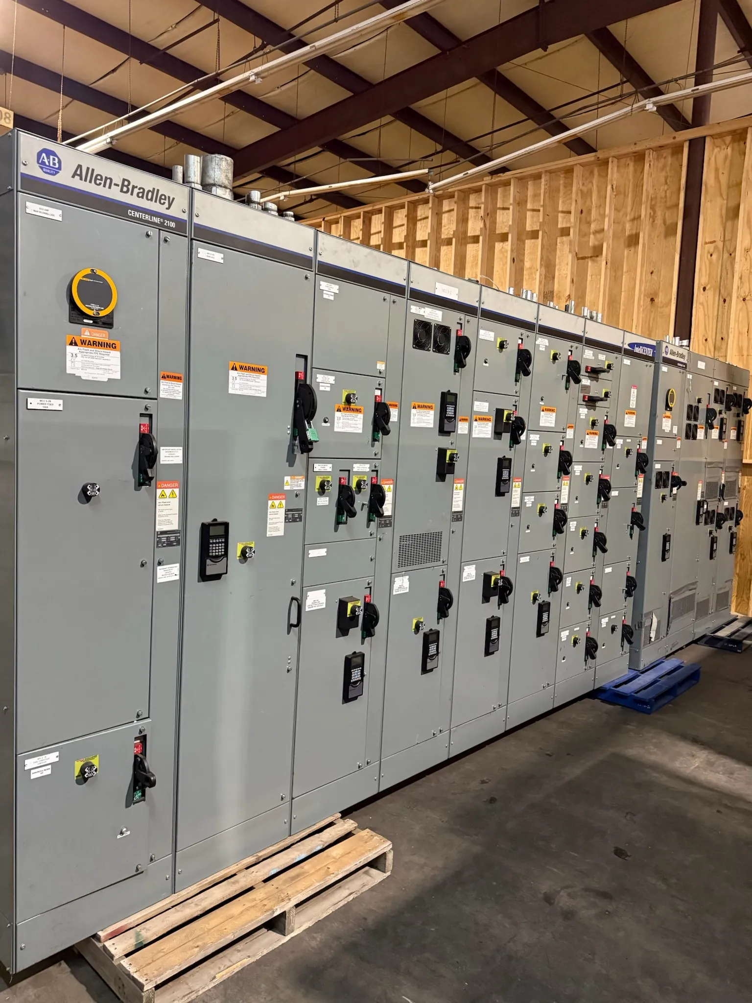
120/208 V selection begins with the system, not the label
A 120/208 V distribution assembly is intended for a particular low-voltage system arrangement; the marking alone does not establish what a facility can connect. In a common three-phase, four-wire wye system, 120 V is available phase-to-neutral and 208 V phase-to-phase. That relationship can serve line-to-neutral loads alongside three-phase or line-to-line loads, but only when the source configuration, neutral arrangement and equipment ratings match the installation. Confirm the actual service at the point of connection with the facility’s electrical engineer or utility documentation before specifying an assembly.
Choose phase configuration and neutral treatment deliberately
Three-phase, four-wire distribution is often considered where a building has a mix of 120 V branch loads and 208 V equipment. The design team should identify whether the switchboard or distribution section receives a neutral, whether it must carry through the assembly, and which outgoing circuits need it. A neutral is not interchangeable with an equipment grounding conductor; their functions and terminations must follow the engineered system design and applicable code. If a project uses a different source configuration, such as a separately derived system or a transformer arrangement, describe that interface rather than assuming a standard four-wire service.
Load balance matters as well as the total connected load. List significant phase-to-neutral loads and three-phase loads so the engineer can assess phase allocation, neutral loading and expected demand. Nonlinear loads, including some electronic power supplies and variable-speed equipment, may affect neutral and thermal design. Their presence should be disclosed for engineering review rather than handled through a generic assumption. Where a neutral is required, its size and the assembly’s neutral bus arrangement need project-specific confirmation.
Separate system voltage from equipment ratings — 120/208 V Switchgear and Distribution
Specify the nominal system voltage as 120/208 V, then provide the required ratings for the equipment and each relevant interface. Voltage describes the system relationship; it does not establish the switchboard’s ampere rating, short-circuit withstand capability, interrupting rating of protective devices, enclosure suitability or available fault current. Those values depend on the source, transformer and upstream protection, conductor and installation details, and the downstream distribution design. Ratings and any applicable product listing must be confirmed for the actual configuration and intended use.
For a low-voltage switchboard, UL 891 may be relevant when the product and application fall within its scope. It is not a blanket statement that every switchgear assembly, voltage class or related product is covered. Identify the requested product type and listing expectations in the quotation package so the manufacturer and project engineer can confirm applicability. Avoid treating a 120/208 V designation by itself as evidence of a particular listing or fault rating.
Confirm available fault current and bus rating together
Available fault current at the equipment location is a key design input. Request the value and basis from the engineer or other responsible source, including the point at which it applies and any assumptions about the upstream system. The assembly’s short-circuit rating and the protective devices’ interrupting ratings must be evaluated in relation to that information and to the specified protective-device arrangement. A higher nominal voltage does not automatically imply a higher fault level, and a bus ampere rating does not state how much fault current the assembly can withstand.
Bus rating should reflect the calculated demand, expected load growth where supported by the project, and the distribution architecture. Main and feeder configurations, number of sections, device types and physical connections can affect the design. Coordination with upstream and downstream overcurrent protection also matters: request the relevant device data and coordination requirements early, particularly where selectivity, service continuity or a specific protective scheme is important. Final choices require qualified engineering review of the complete system, not selection from voltage alone.
Plan load distribution and facility interfaces
For a quotation, provide a load schedule that distinguishes 120 V line-to-neutral loads from 208 V line-to-line and three-phase loads, and indicate which loads are continuous, intermittent or essential under the project’s design criteria. Identify the intended main and feeder arrangement, anticipated circuit count, metering or monitoring needs, neutral requirements, and any space or connection constraints. The manufacturer also needs the installation environment and physical interface information, such as indoor or outdoor location, available working and access space, cable entry direction, mounting conditions and connection to upstream or downstream equipment.
These details are especially important when replacing or extending an existing distribution lineup. Field dimensions, conductor routing, source grounding arrangement and termination requirements should be verified by the project team; apparent similarity between equipment does not guarantee electrical or mechanical compatibility. Nevada sites can differ substantially in building use, ambient conditions and utility service arrangements, so regional location alone is not enough to determine the enclosure, thermal design or incoming configuration.
Prepare a complete, reviewable specification
A useful request identifies the 120/208 V system and phase configuration, neutral and grounding interfaces, calculated load and bus rating, available fault current, protective-device requirements, and the desired product type. Include one-line diagrams, load schedules, equipment location, connection details, applicable project specifications and any required listing criteria. Flag unresolved inputs rather than assigning values by guesswork; the engineering team can determine what further site or utility information is needed before the design is finalized.
We manufacture new custom switchgear and power-distribution equipment in the United States using all-American components, and ship nationwide, including to Nevada. Short lead times are supported, while the schedule for a particular assembly depends on confirmed design scope and project details. A complete, coordinated specification helps establish a suitable configuration and a realistic quotation path. System ratings, listing applicability, interfaces and final selections remain subject to confirmation by qualified engineers and review of the installation conditions.