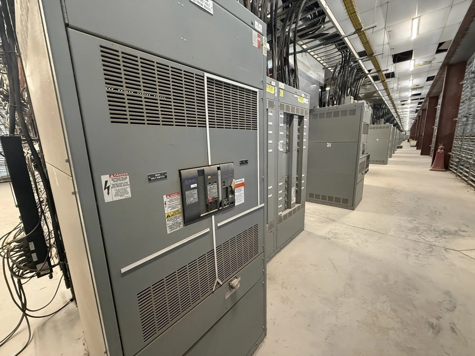
120/240 V Switchgear and Distribution: Confirm the System First
A 120/240 V designation does not, by itself, identify the equipment arrangement a facility needs. Before selecting a switchboard, panelboard, service equipment, or overcurrent protection, confirm the source configuration and how the system is grounded. In a common single-phase, three-wire arrangement, two ungrounded conductors and a neutral provide 120 V line-to-neutral and 240 V line-to-line. Other arrangements, or a project description that simply says “120/240,” may call for different equipment. The one-line diagram, service documentation, and field conditions should agree; a qualified electrical engineer or other responsible design professional should resolve any discrepancy before equipment is specified.
Verify Phase, Conductors, Neutral, and Service Arrangement
Establish whether the source is single-phase or another configuration, and identify the number and function of conductors entering the equipment. Confirm whether a neutral is present, where it is bonded, and whether it must be carried through a particular section. Also determine whether the equipment is service entrance equipment or is supplied downstream from a separate service disconnect. These distinctions affect enclosure arrangement, neutral provisions, grounding and bonding details, and the equipment’s intended role in the distribution system.
Do not infer phase configuration from a voltage label, existing breaker handle, or informal site description. A site may contain more than one source or distribution arrangement, and later modifications may not be reflected in old drawings. Have qualified personnel verify the source and installation details using appropriate project documentation and site review. Manufacturer selection should follow that verified information, not substitute for it.
Match Overcurrent Protection to the Actual Loads
Once the source and conductors are established, identify the connected loads and their supply requirements. Some loads use 120 V line-to-neutral power, others use 240 V line-to-line power, and some facilities have both. The distribution layout must accommodate the intended circuits and conductor connections without assuming that every position, breaker type, or pole arrangement is interchangeable. Equipment schedules should identify the required circuit types, anticipated loads, and any dedicated or special-purpose circuits.
Overcurrent device selection depends on more than nominal system voltage. The responsible engineer must consider conductor ampacity, load characteristics, applicable code requirements, available fault current, and coordination with upstream and downstream devices. Interrupting ratings and short-circuit ratings are equipment characteristics that must be checked against the project conditions; they are not the same as system voltage. Do not select protection from a voltage label alone or presume that an existing device is suitable for a replacement assembly.
Choose Distribution Equipment for Its Intended Role
For a project involving 120/240 V distribution, the appropriate product could be a panelboard, low-voltage switchboard, or other assembly, depending on service configuration, feeder arrangement, circuit count, physical layout, and project specifications. Consider how the equipment connects to the source and downstream loads, how conductors enter and leave the enclosure, and whether the design requires a main device or a particular section arrangement. Available space, access, environmental conditions, and the facility’s installation constraints can also shape the enclosure and layout.
Ratings and product standards must be confirmed for the specific assembly and its intended application. UL 891 applies to applicable low-voltage switchboards; it should not be treated as a blanket designation for every type of distribution equipment. A standard, listing, or rating should be stated only when it is applicable to the selected product and confirmed for the project. Request documentation for the proposed equipment rather than assuming that a voltage class establishes compliance.
Coordinate Interfaces, Fault Duty, and Future Changes
The equipment must fit the electrical system around it. Confirm feeder and load conductor details, lug or termination requirements, grounding and neutral provisions, available fault current at the installation point, and compatibility with upstream protective devices. Selectivity or coordination goals may influence device types and settings, but those decisions require system data and engineering review. Where the facility may add loads or circuits later, identify that need early; spare spaces or provisions should be specified deliberately and must not be treated as a substitute for a verified capacity assessment.
Operational conditions matter, too. Room dimensions, working clearances, routing paths, ambient conditions, and access for installation or future maintenance can affect the equipment arrangement. Nevada facilities vary in location and site conditions, so a shipping destination alone does not establish suitability. The project team should confirm the receiving site’s logistics and installation requirements, including handling access and any environmental considerations relevant to the selected enclosure.
Prepare Clear Inputs for a 120/240 V Equipment Quotation
Useful quotation information includes the verified one-line diagram, phase and conductor configuration, service or feeder role, load and circuit schedule, required equipment type, enclosure and entry preferences, and applicable project specifications. Include available fault-current information, upstream device details, required ratings, and any requested listing or documentation. Drawings should identify the source, neutral and grounding arrangement, and connection interfaces clearly. If any item is unknown or conflicting, flag it for review instead of filling the gap with an assumption.
We manufacture new custom switchgear and power-distribution equipment in the United States using all-American components, with nationwide shipping that can serve Nevada projects. Short lead times are supported, but timing depends on the approved design, component requirements, and project details; no exact schedule should be assumed before review. The equipment configuration, ratings, listing status, and interfaces require confirmation against the project documents and site conditions by qualified professionals before release for manufacture.