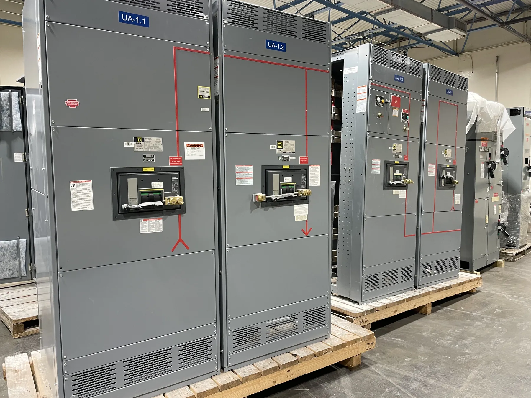
What a 3000 A Rating Means for Switchgear and Switchboards
A 3000 A rating is a design value associated with a specific part of an electrical assembly, not a complete description of its capacity or suitability. It may refer to a main device, a bus, or another defined assembly rating. Those terms are not interchangeable: a 3000 A main does not by itself establish the rating of every bus section, feeder, connection, or downstream circuit. The assembly documentation and equipment nameplate must identify what the stated rating applies to.
For a custom project, engineers compare the proposed rating with the facility’s calculated demand and operating conditions. The rating is not a substitute for a load study, and it does not mean the equipment should routinely carry that amount of load. System voltage, phase arrangement, source characteristics, distribution layout, and the applicable equipment standard all matter. A 3000 A designation is also distinct from system voltage; the voltage and ampacity are separate characteristics that must both be confirmed for the application.
Relating 3000 A Bus Capacity to Calculated Load
Load calculations should reflect the equipment actually served, expected operating patterns, and applicable design requirements. Engineers consider which loads may operate at the same time, whether loads are continuous, and whether the facility expects process changes or added equipment. A total of connected nameplate loads alone may not describe the expected demand. Conversely, assumptions that reduce calculated demand should be supported by the project’s operating plan and engineering criteria.
The bus rating should be selected as part of the complete distribution design. A bus rated 3000 A may be appropriate for a particular calculated load and system arrangement, but the rating cannot be chosen from a headline number alone. Feeder sizes, bus configuration, connection points, and the main protective device must work together. Engineers should also consider how the load is divided among sections and whether normal or alternate sources affect the distribution arrangement.
Continuous Duty, Ambient Conditions, and Installation
Long-duration loading deserves specific review. Where loads operate continuously, the design team must apply the relevant code requirements and equipment instructions rather than assume that a 3000 A rating permits any load profile without further evaluation. The way current is distributed across phases, the characteristics of connected loads, and the intended operating duty can affect the design assessment.
Ambient temperature and installation conditions also matter. Heat from nearby equipment, ventilation, enclosure placement, conductor routing, and the physical room layout can influence thermal conditions. An indoor assembly in a constrained electrical room presents different design questions from equipment installed in a more open environment. Nevada projects may have site conditions that vary by facility and location; the project team should provide actual room or outdoor conditions instead of relying on a general regional assumption. Enclosure selection must suit the installation environment while preserving required clearances and access provisions.
Future Expansion Without Overstating Available Capacity
Planning for future loads can influence bus arrangement, section layout, spare spaces, and feeder provisions. Those choices should be based on a credible expansion plan: likely equipment additions, anticipated load characteristics, available floor area, and the way future circuits may be connected. Leaving physical space for a future feeder does not establish that the source, bus, or protective devices have capacity for it.
Adding load later may require a new calculation and a review of the entire distribution path, including upstream equipment, conductors, protective devices, and fault-current conditions. A nominal 3000 A bus rating should not be treated as uncommitted reserve capacity. The design team should document what is included in the initial scope and what would need engineering review before a later expansion.
Protective Devices, Fault Duty, and Enclosure Ratings
Bus or main ampacity is only one part of equipment selection. The interrupting rating of a circuit breaker, the short-circuit rating or withstand capability of the assembly, and the available fault current at the installation point must be evaluated separately. Protection coordination also requires review of the selected devices, upstream protection, downstream equipment, and the project’s operating requirements. A 3000 A main rating does not establish a particular interrupting rating or guarantee coordination with other devices.
Enclosure characteristics are separate as well. The required enclosure type depends on the installation location and environmental exposure, while the assembly configuration must suit access, cable entry, space, and maintenance constraints. Applicable product standards vary by equipment type. UL 891 applies to applicable low-voltage switchboards; it should not be read as a blanket standard for all switchgear or for medium- or high-voltage equipment. Any required listing, rating, or standard must be confirmed for the exact proposed assembly.
Information Needed to Specify a Custom 3000 A Assembly
For a useful quotation review, provide the one-line diagram, system voltage and source details, calculated load information, and the intended role of the 3000 A rating. Include available fault-current data, protective-device requirements, coordination criteria, feeder and cable-entry needs, enclosure location, environmental conditions, dimensions, and anticipated expansion. Identify applicable project specifications and any required listings, while allowing the engineering review to determine whether the proposed configuration can meet them.
Our U.S.-built assemblies use all-American components, support short lead times, and ship nationwide, including to Nevada. These facts do not establish a particular configuration or delivery schedule. Final ratings, product scope, listings, and project details require confirmation through qualified engineering review and the site-specific design process.