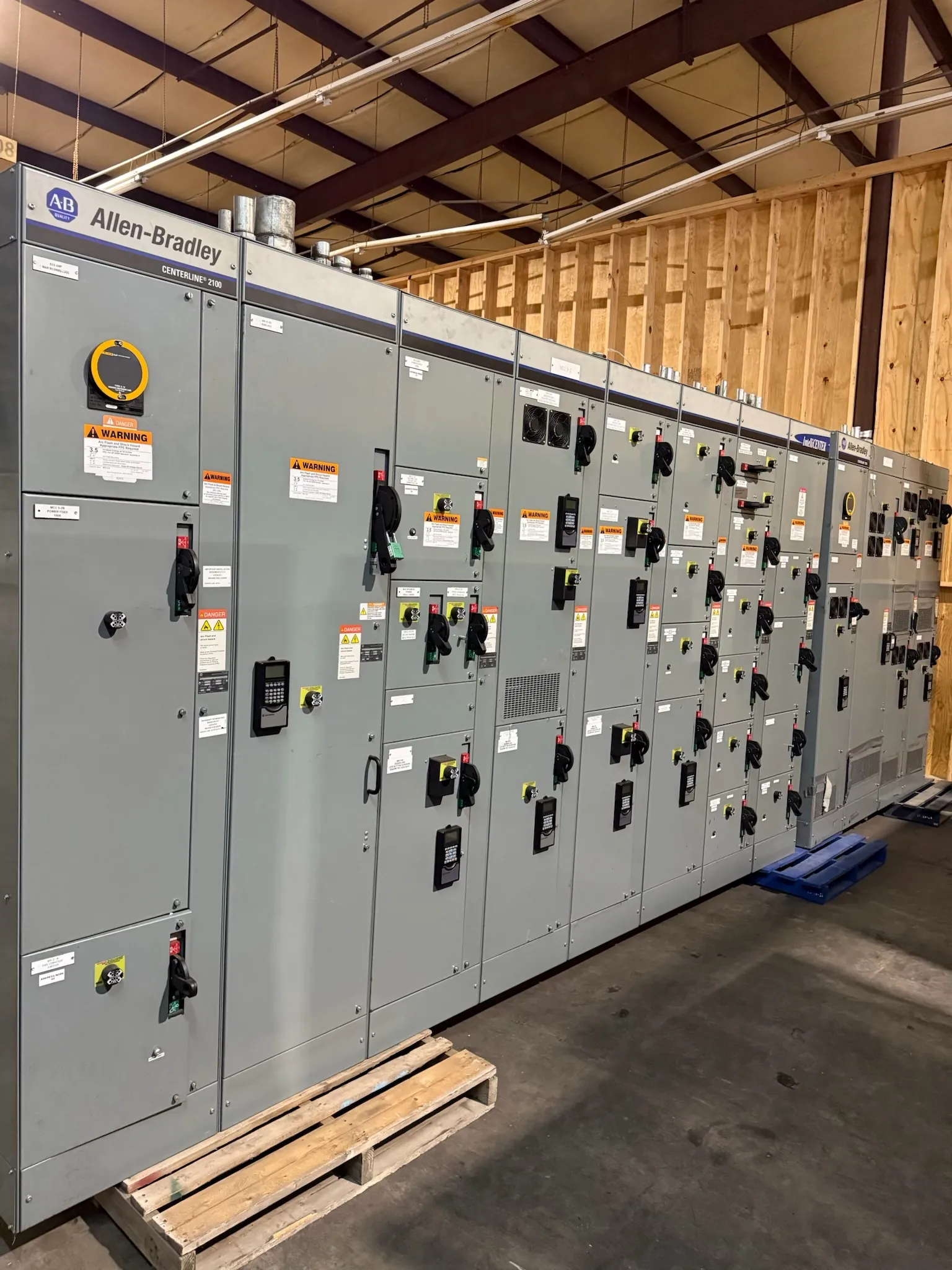
27 kV-Class Metal-Enclosed Switchgear: Start with the Electrical System
Specifying metal-enclosed switchgear for a 27 kV class application begins with the system it must serve—not the class label alone. The nominal operating voltage, the equipment’s maximum voltage rating, insulation requirements, and the system’s grounding arrangement are related but distinct design inputs. Confirm each against the one-line diagram, utility or facility requirements, and applicable engineering documents. A 27 kV class designation does not establish that an assembly is suitable for every system described informally as “27 kV.”
For a Nevada facility, the project team should also identify the installation environment and the electrical service interface. Indoor or outdoor placement, available floor space, cable entry direction, conduit locations, access for maintenance, and site conditions can affect the enclosure and arrangement. Those conditions need review alongside the electrical ratings so the proposed equipment fits both the system and the installation.
Switch, Fuse, or Circuit-Breaker Arrangements
The required switching and protective functions help determine the lineup configuration. A load-interrupter switch with fuses may be considered where the application and protection study support that approach. A circuit-breaker arrangement may be appropriate when the project requires a different interruption, coordination, control, or operating scheme. These are not interchangeable selections based on voltage class alone. The available configurations and their ratings depend on the specific equipment design.
Selection should account for the connected load, transformer or feeder characteristics, expected fault current, protective-device coordination, and the means of control and indication required by the facility. Fuse selection, breaker settings, and upstream and downstream protection must be evaluated as part of the system—not specified in isolation. Qualified electrical engineers should determine the protective design using project information and applicable requirements.
Fault Duty, Insulation, and Grounding
Fault-duty requirements describe the conditions the equipment must withstand or interrupt, as applicable to its design. They are not inferred from “27 kV class,” and they should not be confused with a normal load-current rating. The available fault current, system configuration, protection-clearing assumptions, and the equipment’s documented ratings all matter. Confirm the relevant withstand and interrupting capabilities for the selected arrangement rather than assuming every switch, fuse, breaker, or lineup has the same duty.
Insulation coordination also needs project-specific review. System grounding affects line-to-ground conditions and the requirements applied to insulation and protective devices. The equipment documentation should identify the applicable voltage and insulation ratings for the offered design; an engineer should confirm they match the system’s operating conditions and specified requirements. Grounding provisions, bus connections, and cable termination details should be coordinated with the facility design.
Metal-Enclosed Is Not the Same as Metal-Clad — Metal-Enclosed Switchgear for 27 kV Class
Metal-enclosed and metal-clad describe different construction approaches; the terms should not be treated as synonyms. Metal-enclosed switchgear generally refers to an assembly housed within an enclosure, with its internal arrangement and barriers defined by the product design. Metal-clad construction has a more specific compartmentalized arrangement and construction criteria. Those distinctions can affect equipment layout, maintenance interfaces, and the way devices are separated.
When a specification calls for one construction type, confirm that the proposed product matches the stated requirements rather than relying on a general description or voltage class. Review the equipment drawings and documentation for compartment arrangement, barriers, device construction, and access provisions. A project may have particular requirements for separation or accessibility that must be resolved during design review.
Barriers, Access, and Facility Interfaces
Barrier design and access provisions should reflect the equipment’s intended arrangement and the facility’s operating and maintenance requirements. Consider which compartments require access, how cables and control wiring enter the lineup, and whether the room or outdoor pad provides sufficient working and removal space. The enclosure, doors, partitions, and device locations must be assessed as a coordinated assembly; a general statement that equipment is “barriered” does not describe every compartment or establish suitability for a specific site.
For Nevada projects, shipping and site logistics can influence how a lineup is divided, positioned, and connected. Confirm receiving access, unloading arrangements, route dimensions, installation sequence, and available indoor space with the project team. These are planning inputs, not assumptions about a particular site or delivery schedule.
Information for a 27 kV-Class Switchgear Quote
A useful quotation package identifies the nominal system voltage and grounding, requested maximum equipment voltage and insulation requirements, available and specified fault-duty information, and the preferred switch, fuse, or breaker functions. Include the one-line diagram, protection and coordination criteria, incoming and outgoing feeder details, cable termination preferences, control-power requirements, enclosure location, and any required construction or compartment provisions. Note the governing project specifications and interfaces with transformers, relays, and upstream equipment.
As a U.S. manufacturer of new custom power-distribution equipment, we build assemblies in the USA using all-American components and ship nationwide, including to Nevada. Lead time depends on the confirmed design, component selection, documentation, and project requirements; no schedule should be assumed before review. Final ratings, available configurations, listings where applicable, and project-specific suitability must be confirmed in the equipment documentation and by qualified engineering review.