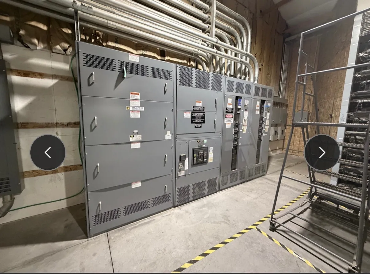
15 kV-Class Metal-Enclosed Switchgear: Start With the System
Specifying metal-enclosed switchgear for a 15 kV class application begins with the electrical system, not the equipment label alone. The class identifies a design category; it does not establish the operating voltage, insulation level, interrupting capability or suitability for a particular installation. Those values must be selected against the system’s nominal and maximum voltage, grounding method, available fault current and operating conditions. A qualified electrical engineer should confirm the design basis and review the site before equipment ratings or configuration are finalized.
Custom equipment from our U.S. manufacturing operation is built with all-American components and can ship nationwide, including to Nevada. Short lead times are supported, but the actual schedule depends on the confirmed design, component selection and project requirements. Product documentation and the approved project specification—not the class designation by itself—should govern final selection.
Switch, Fuse and Breaker Arrangements
A switch-and-fuse arrangement and a breaker arrangement address protection and isolation differently. A fused switch uses selected fuses to interrupt specified fault conditions, while the switch provides a means of making, carrying and interrupting current within its stated duty. Fuse characteristics, available fault current and coordination with upstream and downstream devices all affect whether this approach fits the application.
A circuit-breaker arrangement may provide a different protection and operating scheme, including coordination with protective relays where the design calls for them. Breaker selection must account for its rated voltage, continuous current, interrupting duty and control requirements. Relaying, instrument transformers, trip circuits and communications interfaces should be defined as part of the system design rather than assumed from the 15 kV-class description. The best choice depends on the one-line diagram, protection objectives, operating practices and maintenance plan.
Metal-Enclosed Is Not the Same as Metal-Clad — Metal-Enclosed Switchgear for 15 kV Class
Metal-enclosed switchgear is a broad construction description for equipment housed in metal enclosures. It should not be treated as interchangeable with metal-clad switchgear, which has particular compartmentalization and construction features defined by applicable standards and product specifications. A project that requires metal-clad construction should state that requirement explicitly; the phrase “15 kV metal-enclosed” alone does not establish it.
Barrier and compartment details matter for both equipment selection and maintenance planning. The specification should identify the intended separation among buses, switching or interrupting devices, cable terminations and control components, as applicable to the offered design. Barriers can affect access, inspection, fault containment objectives, equipment dimensions and service procedures. Confirm the actual construction through drawings and product documentation rather than relying on a general enclosure label.
Insulation Level and Short-Circuit Duty — Metal-Enclosed Switchgear for 15 kV Class
Insulation requirements are separate from short-circuit requirements. The insulation level must suit the system voltage and expected electrical stresses, while short-circuit duty must reflect the available fault current and the device’s required interrupting and withstand performance. A 15 kV class designation does not supply these project values or prove that a particular assembly meets them.
Provide the available fault-current information, including the source and point in the system where it applies, for engineering review. The engineer should consider system changes, transformer data, grounding, protective-device clearing behavior and other conditions that affect duty. Equipment ratings, applicable listings and standard conformance must be confirmed for the exact configuration offered. Do not infer that UL 891 applies: that standard concerns applicable low-voltage switchboards, not medium-voltage switchgear generally.
Grounding, Relaying and System Interfaces
Grounding affects fault behavior, protection sensitivity and the equipment connections required at the installation. Identify the system grounding method and any ground-fault protection objectives early. The project team should also define incoming and outgoing cable arrangements, termination requirements, bus connections, control power, metering, interlocks and relay interfaces. These details influence compartment layout and may affect dimensions, access and coordination with adjacent equipment.
Relay functions and settings require a coordinated protection study based on the complete system. Equipment selection alone cannot establish a suitable setting or prove selective operation. Share the one-line diagram, device data and relevant study assumptions so the switchgear design can be reviewed against the intended protection scheme.
Access, Maintenance and Quotation Inputs
Plan access around the equipment’s actual layout and the facility. Nevada installations may involve indoor electrical rooms, outdoor enclosures or constrained delivery routes; ambient conditions, dust, altitude, seismic criteria, available working space and cable-entry direction should be identified when applicable. These conditions can shape enclosure design, ventilation, clearances and service access. Facility planning and equipment handling should be reviewed by qualified project personnel.
For a useful quotation, provide the one-line diagram, system voltage and grounding information, required insulation level, available fault-current data, preferred switch/fuse or breaker arrangement, relay and metering scope, cable and bus interfaces, enclosure environment, access constraints and requested construction requirements. Include any project-specific standards or listing expectations. The final submittal should document the offered ratings, barriers, interfaces and maintenance access so the engineer and owner can confirm that the configuration fits the installation.