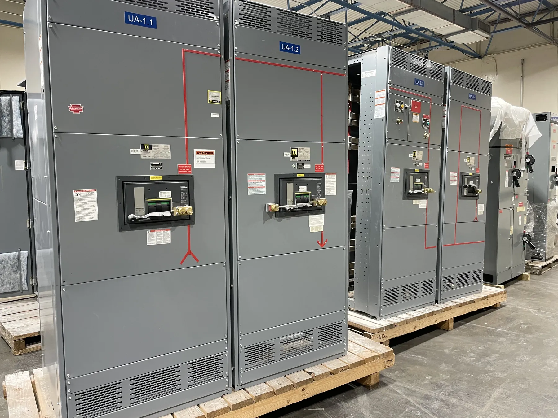
27 kV Class Medium-Voltage Switchgear: What the Class Means
27 kV class identifies an equipment voltage class; it does not establish that the gear is suitable for every system described as 27 kV. The nominal system voltage, maximum voltage the equipment must withstand, grounding arrangement, and expected operating conditions all matter. A class label alone does not confirm compatibility with a particular installation. For a specification or quotation, provide the actual system voltage and relevant utility or facility requirements so the design can be evaluated against the intended application.
It is also important to distinguish system voltage from equipment ratings. A system’s nominal voltage describes the electrical network, while equipment maximum voltage and insulation ratings describe limits and withstand capabilities defined for the switchgear. Those values are related, but they are not interchangeable. Confirm the ratings shown on the proposed equipment documentation rather than inferring them from “27 kV class.”
Fault Duty Must Match the Installation
Available fault current is a key input to selecting medium-voltage switchgear. The required interrupting and withstand capabilities depend on the electrical system and the point where the gear will connect, not simply on the voltage class. Fault levels can vary with utility sources, transformers, generators, motors, and changes to the facility configuration. Engineering review should establish the applicable duty and verify that the proposed equipment ratings and protective devices are appropriate.
For quotation and design review, identify the available fault-current information, source and transformer data, and any known future changes that could affect the system. If a study or utility information is not yet available, flag that gap rather than treating an assumed value as final. A qualified electrical engineer should confirm the design basis and coordination requirements for the specific site.
Insulation Level and Environmental Conditions
Insulation selection is not determined by a voltage-class label alone. The required insulation level must be checked against the system voltage and the equipment’s specified maximum voltage and withstand ratings. Installation conditions can also affect the design basis, including indoor or outdoor placement, altitude, ambient temperature, contamination, moisture, and exposure to corrosive or dusty conditions. These factors should be stated in the project requirements so the equipment configuration can be reviewed for the actual environment.
Facility constraints matter as well. Access routes, room clearances, cable-entry direction, available floor space, and the location of adjacent equipment can influence lineup arrangement and interfaces. Providing room drawings or dimensional limits early can help identify conflicts before the switchgear configuration is finalized.
Protective Relays and System Coordination — Medium-Voltage Switchgear for 27 kV Class
Relay functions and settings should reflect the system protection philosophy, connected equipment, and coordination study. The specified relays may need to work with upstream and downstream protective devices, transformer protection, utility requirements, or facility control and monitoring systems. Relay selection alone does not establish a coordinated protection scheme; device characteristics, instrument-transformer inputs, trip circuits, and setting responsibilities must be reviewed together.
Useful quotation inputs include required protective functions, preferred relay platforms if specified, communications protocols, control-power requirements, alarm and status points, and any integration constraints. Confirm who will provide final settings and how those settings will be validated. Changes to sources, transformer impedance, cable lengths, or connected loads may affect coordination and should be communicated to the project engineer.
Cable Terminations and Connection Interfaces
Cable termination requirements shape the switchgear interface. Specify cable type, conductor material and size, number of conductors per phase, shielding details, termination style, entry direction, and any limits on bending space. The equipment design must accommodate the intended cable terminations and clearances; assumptions about these details can result in installation difficulties even when the voltage and fault ratings are otherwise suitable.
Also identify whether the connection is incoming, outgoing, or tied to other equipment, and provide interface drawings where available. The completed design should be checked against the cable manufacturer’s requirements, applicable project standards, and the site layout. Final termination details and clearances require engineering review.
Documentation, Configuration, and Quotation Review
Custom medium-voltage switchgear is manufactured to an approved project configuration. A useful request for quotation includes system voltage, required equipment maximum voltage and insulation level, available fault duty, relay and control requirements, cable interfaces, environmental conditions, and dimensional constraints. Include the one-line diagram, applicable specifications, and known utility or facility requirements when available. Missing inputs can affect configuration and should be identified for resolution, not silently replaced with assumed ratings.
Before release, review the equipment documentation for the actual ratings, protective devices, interfaces, and stated configuration. Listings, ratings, and project-specific details must be confirmed against that documentation and the approved design. UL 891 applies to applicable low-voltage switchboards; it should not be used to characterize medium-voltage switchgear. This manufacturer builds new custom power-distribution equipment in the United States using all-American components and ships nationwide, including to Nevada. Lead time depends on the confirmed scope and project requirements.