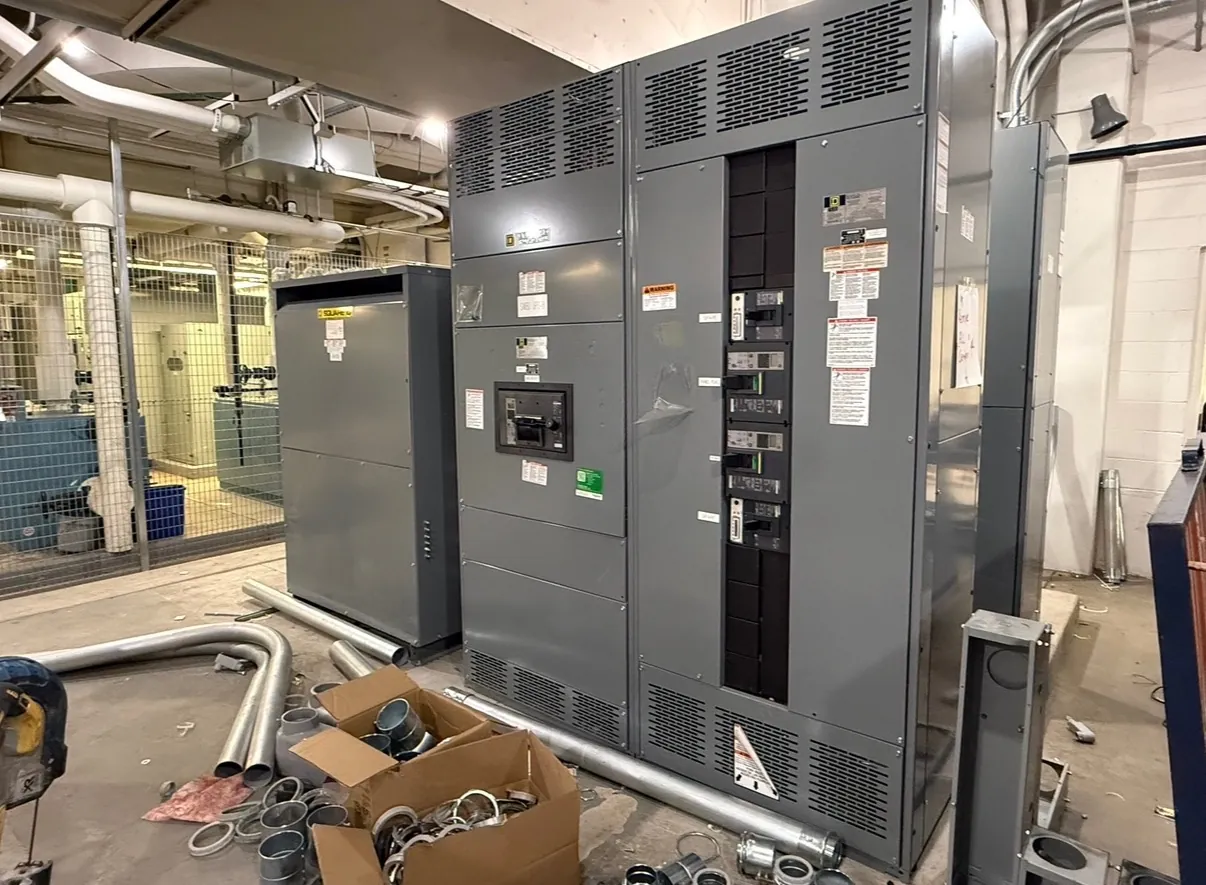
Pad-Mounted Switchgear for Yerington, Nevada Projects
Pad-mounted switchgear can provide an outdoor point for controlling and isolating portions of a distribution system while keeping switching components enclosed. For a Yerington project, the equipment arrangement should follow the actual one-line diagram, source configuration, load requirements and utility interface—not a generic city-based specification. A manufacturer can build new custom equipment for the defined application and ship it to Nevada. Before a design is finalized, the project team should confirm the required functions, ratings, physical layout and applicable standards with qualified electrical engineers and the serving utility.
Enclosure, Site Exposure and Equipment Access
The enclosure selection affects weather protection, equipment arrangement, cable access and the space needed for inspection and maintenance. Specify the intended installation environment and any known exposure to dust, precipitation, irrigation, standing water, direct sun, wind or corrosive conditions. These conditions can influence enclosure materials, finish, ventilation approach and access features. Do not treat an outdoor enclosure rating as proof that every site condition is addressed; the enclosure and its installed interfaces must be reviewed for the actual location.
Plan working and access space around doors, operating features and cable compartments. Account for fences, walls, vehicle paths, landscaping and other equipment that could obstruct access or create a conflict. The selected footprint must also fit the equipment arrangement, cable bend space and foundation. Any dimensions and clearances shown for a proposed assembly should be checked against the site plan and the applicable project requirements.
Foundation and Cable-Entry Planning — Pad-Mounted Switchgear in Yerington, NV
The concrete foundation or other support arrangement must suit the equipment’s footprint, weight, anchorage needs and cable-entry design. Coordinate foundation drawings with civil and electrical plans before construction. Confirm finished grade, drainage, conduit locations and entry elevations so cables can reach their terminals without forcing tight bends or crossing incompatible compartments. Site conditions and structural requirements should be reviewed by the responsible design professionals; a general equipment description cannot establish foundation dimensions or reinforcement.
Identify whether conductors enter from below or through another project-defined route, and document conduit sizes, locations, conductor types and termination requirements. The switchgear layout needs to accommodate the intended cable count and routing while preserving access to components. A mismatch between conduit placement and the equipment’s compartment arrangement can require field changes, so cable schedules and foundation openings should be coordinated with the final equipment drawings.
Utility Interface, Ratings and Protection Coordination
The utility point of connection is a central design input. Confirm the source arrangement, ownership boundary, metering needs, required switching functions and utility-specific interface requirements with the serving utility and project engineer. Utility requirements can differ by application and should not be assumed from another installation. The switchgear manufacturer needs clear, approved interface information to develop equipment that fits the intended system.
Specify system voltage separately from equipment ratings. Also provide available fault-current information, continuous load expectations, protective-device requirements and the intended operating configuration where known. Ratings describe equipment limits and must be selected for the application; they do not, by themselves, establish that the equipment is suitable for a particular system. Protection coordination, grounding, switching functions and any arc-flash evaluation require qualified engineering and site-specific review. Applicable listings and standards must be confirmed for the particular product and configuration. UL 891 applies to applicable low-voltage switchboards; it should not be taken as coverage for all pad-mounted switchgear or other product types.
Plan for Load Growth and Future Circuits
For a Yerington project, record both the planned load and the expected direction of future growth. List spare circuits or ways needed at initial installation, as well as circuits that may be added later. Note which loads are essential, how they are expected to be supplied and whether future extensions would change the source arrangement or protection scheme. This information helps the design team assess space, bus arrangement, compartments and interfaces before the enclosure is fixed.
Future capacity is not just unused space. A later extension may depend on electrical ratings, available source capacity, compatible equipment and utility approval. Provide a realistic expansion concept, including the equipment location and any clearances that must remain available. The project engineer can evaluate whether the proposed spare provisions fit the system and whether later work would require a different arrangement.
Quotation Inputs and Equipment Coordination
A useful quotation package includes the one-line diagram, site layout, utility requirements, system data, load schedule, cable information, environmental conditions and anticipated expansion needs. Include preferred enclosure dimensions or site limits when established, along with any project specifications and required submittals. Flag unresolved details rather than filling gaps with assumptions. This allows the manufacturer and engineering team to identify decisions that affect the assembly before drawings are prepared.
The manufacturer builds new custom power-distribution equipment in the United States using all-American components and supports short lead times, with nationwide shipping that includes Nevada. Actual design, listing applicability, ratings, schedule and delivery arrangements depend on the approved project requirements and must be confirmed for the specific order. Coordinate equipment drawings with the civil contractor, electrical contractor, utility and design engineer before foundation work or cable installation proceeds.