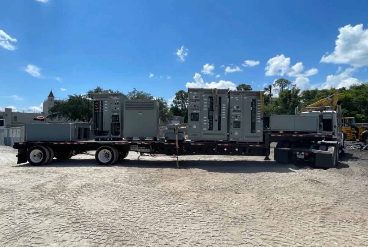
Motor Control Centers for Yerington, NV Projects
A motor control center (MCC) groups motor-control units, feeder devices and related equipment into an organized assembly. For a Yerington facility, the design should reflect the actual motors and loads to be served, the electrical system available at the installation point, and the room provided for the equipment. A new custom MCC can be configured around those project requirements rather than treated as a generic enclosure selection.
Useful early inputs include the motor list, nameplate information, starting methods, operating duty, control-voltage requirements and the intended location. Environmental conditions, cable entry direction, working clearances and access for moving sections into the building can also affect the layout. The equipment is manufactured in the USA using all-American components and can ship nationwide, including to Nevada; shipping arrangements and site access should be addressed during project planning.
Starter and VFD Choices Should Follow the Load
Motor starters and variable-frequency drives (VFDs) serve different operating needs. A starter may be appropriate where a motor runs at a fixed speed and the process calls for straightforward starting and stopping. A VFD can provide adjustable speed or process control, but introduces requirements for drive sizing, heat management, control interfaces and coordination with the motor and driven equipment. The right choice depends on the application, not simply on whether a drive can fit in the MCC.
For each motor, identify the required control method, expected starting behavior, interlocks, local controls and signals exchanged with a plant control system. Drive bypass arrangements, isolation needs and communications protocols should be specified where applicable. VFD compatibility with the motor, cable installation and operating conditions should be reviewed by the project’s qualified electrical and controls professionals. The MCC layout must also account for drive heat dissipation and separation from other units as required by the equipment design.
Short-Circuit Ratings and Feeder Protection Need Coordination
An MCC’s short-circuit rating is not the same thing as the system voltage, and neither should be inferred from a general product description. The project team needs to establish the available fault current at the proposed equipment location, the system voltage and configuration, and the protective devices upstream and within the assembly. The selected rating and device combination must suit the installation and be confirmed through engineering review.
Feeder protection should be considered alongside motor branch-circuit protection. The design needs to address the loads supplied from the MCC, conductor and equipment requirements, and coordination with upstream protective devices where applicable. Changes in a facility’s electrical system can affect fault-current and coordination assumptions, so drawings and one-line information should represent the conditions relevant to the project. Final selections require qualified engineering and site review; a rating cannot be established from location alone.
Plan Load Growth, Spare Circuits and Future Space
Yerington project planning should record both present demand and anticipated load growth. Identify which motors or process areas may be added, expanded or converted to VFD operation, and when that change is expected. This information helps distinguish a genuinely useful spare circuit from an unspecified allowance that may not fit a future motor’s requirements.
Also document the number and type of spare circuits, any reserved section space, and whether future extensions must connect to the existing assembly. A future addition may depend on bus capacity, available fault-current rating, physical alignment, access and the original assembly’s design. Reserving floor area is not a substitute for confirming those electrical and mechanical interfaces. Keeping a current equipment schedule and drawings can make later evaluation more efficient.
UL 845, Access and Maintenance Considerations
Ask the project engineer or specification authority whether UL 845 is required for the MCC and what documentation or listing scope applies to the proposed assembly. Requirements can depend on the project specification and application. Do not assume that a standard associated with motor control centers applies to every equipment type or establishes all project ratings. Applicable listing status, construction details and ratings should be confirmed for the specific quoted configuration.
Maintenance access should influence section arrangement, device selection and room planning. Consider how personnel will reach units and wiring compartments, inspect identification, and service equipment in accordance with the manufacturer’s documentation and site requirements. Verify working space, door swing, cable routes and ventilation provisions against the installation conditions. A site review by qualified personnel can identify obstructions or environmental constraints that are not evident in a one-line diagram.
Information to Prepare for a Yerington MCC Quote
A useful quotation package includes the motor and feeder schedules, system voltage and available fault-current information, one-line diagram, control schematics or interface requirements, and the project specification. Include starter and VFD preferences, feeder-protection expectations, required rating and listing information, enclosure and cable-entry needs, and any known room dimensions or access restrictions. Note planned load growth, spare-circuit quantities and space reserved for extensions.
Custom equipment details, ratings, listing requirements and delivery planning must be confirmed for each project. Clear, current inputs help align the proposed MCC with the facility’s electrical design and operating needs before manufacturing begins.