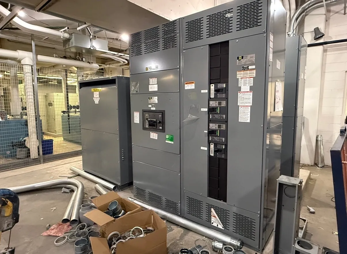
Wastewater Switchgear for Yerington Pumping and Treatment Facilities
Wastewater electrical distribution in Yerington has to account for the equipment that moves and processes flow, not just the nominal service voltage. Pumps, motors, screens, aeration equipment, controls, and building loads can have different operating patterns and starting characteristics. A custom switchboard or switchgear assembly should be developed around the project’s one-line diagram and load information so that feeder provisions, protective devices, and interfaces suit the actual facility. The right configuration depends on the service, the equipment lineup, operating sequence, and applicable project requirements.
For municipal and other wastewater projects, continuity of operation is an important design consideration. The distribution arrangement may need to support normal utility power, standby generation, or other specified sources. How those sources connect—and whether transfer equipment, interlocking, metering, or control interfaces are needed—must be established with the project engineer and equipment suppliers. A manufacturer can build to an approved design and documented requirements; it cannot determine a facility’s operating philosophy or electrical design without qualified engineering review.
Motor Loads, Feeders, and Protective Device Coordination
Pump and motor loads influence feeder sizing, overcurrent protection, and the physical arrangement of distribution equipment. The project team should identify motor ratings and starting methods, any variable-frequency drives or soft starters, expected simultaneous operation, and the protective devices specified for each circuit. Drive-fed motors can introduce requirements for coordination between the switchgear, drive, bypass provisions if applicable, and the motor’s control system. These details affect not only the selected components but also available sections, cable entry, heat dissipation, and future service access.
Protection should be coordinated across the facility’s distribution system rather than selected in isolation. The service characteristics, available fault current, upstream devices, downstream equipment, and required settings all matter. Ratings such as voltage, current, and short-circuit withstand are distinct design values; they must not be inferred from one another. Engineers need to verify the system conditions and applicable requirements before equipment ratings and protective-device selections are finalized.
Standby Power and Control-System Interfaces
If standby generation is part of a Yerington wastewater project, provide the generator and transfer-system information early. Relevant inputs include the source arrangement, generator output, transfer method, grounding and bonding design, and the loads intended to operate during an outage. Large motor starts can affect generator selection and the order in which loads are restored, so generator capability and pump sequencing should be reviewed together by the responsible engineers. The switchgear configuration must reflect the approved source and control scheme; it should not assume that every load can operate at once on standby power.
Control interfaces also deserve careful definition. Identify which signals are exchanged with pump controls, programmable controllers, building systems, and remote monitoring equipment, and clarify who furnishes each component and connection. Terminal locations, control power, communications provisions, and wiring boundaries can be documented in the submittal process. Clear interface responsibility helps avoid gaps between the distribution assembly, controls integrator, generator supplier, and installing contractor.
Moisture Exposure, Corrosion, and Enclosure Selection
Wastewater facilities may include dry electrical rooms as well as areas exposed to condensation, washdown, airborne contaminants, or outdoor weather. Conditions vary by installation, so enclosure selection should follow the actual location and exposure—not the facility name alone. The specified enclosure rating should match the environment and installation conditions, with the project team confirming whether ventilation, heaters, coatings, material choices, or other provisions are appropriate. Moisture management also depends on room design, cable penetrations, drainage, and maintenance practices outside the switchgear itself.
For Yerington, the equipment location, seasonal conditions, building construction, and distance from process areas can all shape the practical design. Provide the intended indoor or outdoor placement, ambient conditions, access constraints, and any known corrosive or wet exposure during specification development. A qualified engineer and the manufacturer can then review enclosure and construction details against the project documents. No enclosure rating should be assumed to address every environmental condition.
Plan Load Growth, Spare Circuits, and Future Space
Future capacity is more useful when it is specified concretely. Record anticipated load growth, the circuits that should be installed as spares, and the physical space available for future extensions. Distinguish an unused breaker position from a fully provisioned spare feeder: they are not necessarily equivalent in hardware, bus capacity, wiring space, or documentation. Identify which future loads are known, their approximate characteristics where available, and whether expansion must occur without changing adjacent equipment.
Room dimensions, working clearances, doorway access, cable routing, and the location of existing equipment can limit an otherwise suitable lineup. Share layout drawings and cable-entry preferences so the proposed arrangement can be checked against the site. Future extension plans should also be reviewed for compatibility with the intended assembly and installation; available space alone does not establish electrical capacity.
Information for a Yerington Wastewater Equipment Quote
A useful quotation package includes the one-line diagram, load schedule, service data, fault-current information when available, equipment ratings, enclosure requirements, and project specifications. Add motor and drive details, standby-power and transfer requirements, control-interface responsibilities, site layout, cable-entry direction, and the requested spare circuits or extension provisions. Include the project schedule and submittal requirements, but do not treat a quoted lead time as confirmed until the design, scope, and manufacturing schedule have been reviewed.
We manufacture new custom power-distribution equipment in the United States using all-American components and can ship nationwide, including to Yerington. The final configuration, ratings, listing applicability, and project-specific details require confirmation against the approved documents and qualified engineering review. For low-voltage switchboards, UL 891 may apply when the product and project requirements call for it; it does not cover every type of switchgear or every assembly. Clear project inputs help align the equipment with wastewater operations, site conditions, and planned growth.