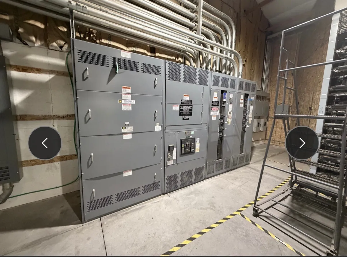
Utility Switchgear for Yerington, NV, Starts With the Service Requirements
A utility distribution project in Yerington needs equipment coordinated with the requirements of the serving utility and the conditions at the specific site. Before selecting a switchboard or other distribution assembly, establish where utility responsibility ends and customer responsibility begins. Document the service arrangement, point of connection, planned load, system characteristics, and any utility-issued design or acceptance criteria. These details guide equipment selection; a general product description cannot substitute for the utility’s project requirements or a qualified engineering review.
For a new facility, expansion, or service modification, identify the loads that will be connected initially and those anticipated later. Record expected load growth and the timing of planned additions, rather than sizing only around the first phase. This information helps the design team evaluate bus and feeder needs, protective-device provisions, physical dimensions, and whether the proposed assembly can accommodate the intended arrangement. Ratings are not the same as system voltage, and both must be confirmed for the application.
Interconnection, Metering, and Utility Acceptance
Interconnection details affect both equipment configuration and project responsibilities. Confirm the utility’s required service configuration, connection point, conductor arrangement, and interface boundaries before requesting a final quotation. The utility may specify where service conductors terminate, how metering is arranged, which compartments or provisions are needed, and what submittals it expects to review. Requirements vary by utility and project; do not assume that a familiar configuration will be accepted at another service location.
Metering should be coordinated early with the serving utility and the project engineer. Determine whether metering equipment is utility-furnished, customer-furnished, or integrated into a larger assembly, and identify the required physical and electrical interfaces. Metering provisions can affect compartment layout, access, wiring routes, and enclosure dimensions. Any utility acceptance or approval remains specific to the project and must be confirmed with the utility; it should not be inferred from a product’s general description.
Protection, Fault Duty, and Grounding Coordination
Protective-device selection depends on the system study, available fault current, load characteristics, upstream and downstream equipment, and the utility’s coordination requirements. Share the applicable study information and protection criteria with the engineer responsible for the design. Device type, ratings, trip functions, and coordination approach should be evaluated together; selecting a component based on a nominal system voltage alone does not establish that the complete assembly is suitable.
Grounding and bonding also require project-specific review. Provide the grounding arrangement, service configuration, site grounding information, and any utility criteria available during design. These determine how the equipment interfaces with the electrical system and how grounding provisions are laid out. Final design decisions belong with qualified electrical professionals who can review the complete system and site conditions, not with an equipment description considered in isolation.
Plan for Load Growth, Spare Circuits, and Future Space
For Yerington projects, make future needs explicit in the equipment schedule. List spare circuits separately from planned loads, indicate which future loads are reasonably foreseeable, and describe whether later work may require an extension of the assembly or additional distribution sections. A spare circuit position is not automatically the same as capacity for future load: the bus, protective devices, service rating, fault-duty requirements, and physical arrangement all need review against the anticipated expansion.
Space for future extensions is a practical design choice with tradeoffs. Reserving room may affect the initial footprint, enclosure arrangement, conductor entry, and access to adjacent equipment. If an extension is contemplated, identify its direction and interface assumptions, including how the future section would connect and what site space must remain clear. The design team should verify that the chosen arrangement supports the intended plan and complies with applicable utility and project requirements.
Site Conditions and Delivery Planning in Yerington
Site details help avoid mismatches between a manufactured assembly and its installation location. Provide the available equipment-room or outdoor footprint, access route, installation orientation, conductor entry preferences, and relevant environmental conditions. Note constraints such as limited working area, adjacent equipment, building access, or sequencing with other construction. These are project inputs, not assumptions about Yerington facilities; conditions must be verified at the actual site.
Equipment is manufactured in the United States using all-American components and can ship nationwide, including to Nevada. Delivery planning should account for the destination, receiving arrangements, unloading capability, site access, and construction schedule. Short lead times are supported, but timing depends on the finalized design, component selection, approvals, and order details. Confirm schedule expectations for the specific configuration rather than relying on a general lead-time assumption.
Information to Provide for a Useful Quotation — Utility Switchgear in Yerington, NV
A complete quotation request gives the manufacturer and project team enough context to evaluate the proposed assembly. Include the one-line diagram, service and system information, load schedule, planned growth, spare-circuit requirements, available fault-current or study data, utility metering and interconnection criteria, grounding requirements, and site dimensions. Identify applicable specifications and any required submittals, drawings, or review milestones. State whether the equipment is a low-voltage switchboard where UL 891 may apply; that standard is not a blanket designation for every type of switchgear, and applicability, listing, ratings, and project details must be confirmed for the selected product.
With these inputs, the design can be developed around the actual utility interface and the Yerington site rather than a generic layout. Qualified engineers and the serving utility must resolve system design, acceptance, and coordination questions before equipment details are finalized. Clear requirements at the quotation stage also help align the assembly’s configuration, future provisions, and delivery planning with the project’s intended use.