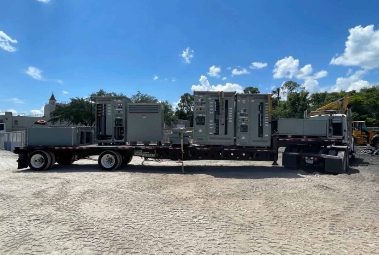
Manufacturing Switchgear for Yerington Production Facilities
Manufacturing operations depend on electrical distribution that fits the production process, not just the building’s service entrance. A switchboard or related distribution assembly for a Yerington facility may need to serve process equipment, motor loads, building systems and planned production growth, each with different operating demands. Early planning helps align the equipment configuration with the project’s electrical design, available space and installation schedule.
Start by documenting the facility’s existing and planned loads, including major motors, production lines, heating and cooling equipment, and other significant electrical demands. Load information should reflect expected operating conditions rather than a simple list of nameplate values. A qualified electrical engineer can assess demand, system conditions and applicable requirements, then establish the ratings and configuration appropriate to the project.
Plan Around Motors, Production Loads and Controls
Motor-driven processes can affect distribution choices because starting methods, operating patterns and control arrangements vary by application. Identify which motors run continuously, which start or stop frequently, and which equipment must coordinate with other parts of a production line. These details give the project team a clearer basis for determining feeder arrangements and interfaces with motor-control equipment.
Switchgear and switchboards do not automatically include every motor controller, drive or control function a plant needs. Define which components are part of the distribution assembly and which are furnished or engineered separately. Clarify control wiring, communications, protective devices and enclosure or environmental requirements with the responsible design team. The right division of scope can reduce interface gaps during procurement and installation.
Match Ratings to the Electrical System — Manufacturing Switchgear in Yerington, NV
Equipment ratings must be evaluated against the actual system voltage, available fault current, conductor arrangements and other site-specific conditions. A rating is not, by itself, a statement of system voltage or proof that an assembly suits a particular installation. The project’s engineer should confirm the required ratings and protective-device coordination using current design information and the applicable codes and standards.
For applicable low-voltage switchboards, UL 891 may be relevant to the specification. It does not apply universally to every type of switchgear or to medium- or high-voltage equipment. Confirm the intended product type, required listing, configuration and project documentation before finalizing a specification. Listings and certifications should be verified for the particular equipment offered; they should not be assumed from a general product description.
Reserve Feeder Capacity and Physical Space
Future production plans can influence today’s layout. Record anticipated load growth, the spare circuits the facility expects to need, and the space available for future extensions. Spare circuit positions, provisions for additional distribution sections and physical room to expand are related but distinct considerations. An assembly may have electrical capacity without a practical path for adding equipment, or available floor area without suitable space in the lineup.
Share room dimensions, access routes, equipment location and known constraints with the design and manufacturing teams. In an existing plant, nearby piping, structural elements, ventilation, doors and the movement of production equipment can shape what can be installed. For a Yerington project, verify transport access and receiving arrangements at the facility as well as the electrical-room conditions; local logistics and site readiness can affect sequencing without changing the need for engineering review.
Coordinate Uptime Needs and the Shutdown Sequence
Before selecting an installation approach, identify which production areas can be taken out of service, when interruptions are feasible and which loads require a separately engineered continuity plan. A new assembly alone does not establish how a facility will maintain operations during a changeover. The project team must review existing distribution, temporary arrangements if applicable, switching interfaces and the planned sequence of work.
Build the shutdown sequence around confirmed scope, equipment delivery, site preparation, installation responsibilities and required inspections or approvals. Existing drawings may not reflect later modifications, so field verification by qualified personnel is important. Do not assume that a planned outage, connection method or protective-device setting is suitable until the responsible engineers and facility representatives have reviewed the site and design.
Prepare a Useful Project Specification
A quotation request is more actionable when it includes the one-line diagram, equipment scope, system information, load schedule, required ratings, preferred arrangement and relevant site constraints. Also provide the planned load growth, spare-circuit expectations, available space for future extensions and target shutdown sequence. Identify interfaces with motor controls, upstream and downstream equipment, monitoring systems and the project’s installation contractor. Open questions can then be resolved before they become schedule or scope conflicts.
Custom assemblies are manufactured in the United States using all-American components, with short lead times supported and shipment available nationwide. Actual timing depends on the approved design, component requirements and project coordination. For Yerington facilities, confirm delivery access, receiving capacity and installation readiness with the project team. Final equipment selection, ratings and documentation require review against the specific electrical design and site conditions.