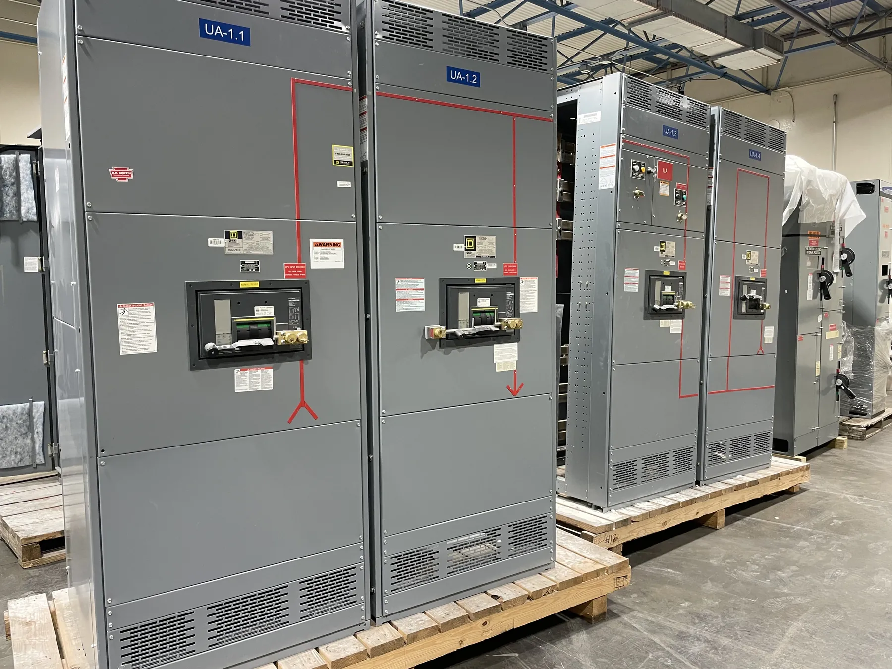
Planning Pad-Mounted Switchgear for a Winnemucca Project
Pad-mounted switchgear can bring switching and distribution functions together in an outdoor enclosure, but the right configuration depends on the electrical design and the site around it. For a Winnemucca project, start with the intended role of the equipment: the connected system, incoming and outgoing circuits, operating arrangement, and coordination with the utility or other system owner. Those inputs shape the enclosure, cable compartments, switching provisions and ratings. A manufacturer can build new custom equipment to an approved project specification; it cannot determine a suitable design from the city or product name alone.
Site planning matters as much as the equipment schedule. Confirm where the assembly will sit, how crews and delivery vehicles can reach it, and what space is available for installation and future access. Local weather exposure, dust, precipitation, temperature range, drainage and potential contact with water can affect enclosure details and material choices. These conditions should be documented for engineering review rather than assumed from a general description of Winnemucca.
Outdoor Enclosure and Environmental Protection — Pad-Mounted Switchgear in Winnemucca, NV
The enclosure protects internal components from outdoor exposure while providing access for installation, inspection and operation. Project requirements may call for particular compartment arrangements, barriers, door and access features, finish, or provisions for cable terminations. The enclosure should be selected with the actual environment and the equipment’s intended use in mind. Environmental protection is not a substitute for suitable site drainage, foundation design or maintenance planning.
Describe the installation location clearly: exposed or sheltered, near roadways or other sources of dust, and subject to any known corrosive, chemical or physical hazards. Also identify constraints on access and clearance. These details help the design team evaluate enclosure construction and layout without treating a generic outdoor designation as proof that every condition has been addressed.
Foundation, Cable Entry and Utility Interfaces
Pad dimensions, equipment footprint, mounting details and conduit locations must be coordinated with the civil and electrical drawings. Foundation design belongs with the project’s qualified design team, which can account for site conditions, structural loads, drainage and applicable requirements. Before equipment release, compare the approved foundation plan with the switchgear outline and cable-entry layout. A mismatch can complicate conduit alignment, cable pulling and final placement.
Identify cable approach direction, quantity and type of conductors, termination requirements, phase arrangement and any space constraints in the cable compartments. Clarify whether entry is from below or another specified route, and coordinate conduit locations with the manufacturer’s drawings. Utility interfaces also need early attention: identify the serving utility or system owner, ownership boundaries, required switching arrangement, interface details and review process. Utility acceptance or approval must not be assumed; it is specific to the project and responsible organization.
Ratings and Equipment Configuration
Ratings are design inputs, not interchangeable labels for system voltage. The project team should provide the applicable system information and specify required ratings for the equipment and its components, including the relevant voltage, continuous-current and fault-duty requirements. The manufacturer and qualified engineers must confirm that the proposed configuration is appropriate for the system and the available fault conditions. Product ratings, listings and project-specific details require confirmation against the final design.
Other configuration choices may include the number and function of ways, switching devices, fusing or protective-device provisions, metering interfaces, control features and connection points. Each choice affects compartment layout, cable space, interfaces and coordination with upstream and downstream equipment. UL 891 applies to applicable low-voltage switchboards; it should not be read as a blanket standard for all pad-mounted switchgear or every product configuration. Any requested listing or standard must be confirmed for the specific equipment.
Receiving, Unloading and Section Shipping Limits
Plan delivery around the installation schedule, not just the desired arrival date. Confirm the receiving location, access route, unloading equipment and responsible receiving personnel before shipment. Check transport access for road restrictions, turning space, overhead obstructions and the final route to the foundation. Site readiness should include a verified pad, prepared conduit interfaces and a clear placement area.
Ask the manufacturer to identify the shipping configuration, handling points, overall dimensions and weight, and any limits on lifting or moving the assembly. If the design ships in sections, establish how each section will be received, staged, aligned and joined at the site, and whether the site’s unloading equipment can handle each shipment. Coordinate these limits with the installation contractor and schedule so that equipment is not delivered before secure storage or placement is available.
What to Provide for a Winnemucca Quote
A useful quotation request includes the one-line diagram, equipment schedule, system and rating requirements, circuit functions, cable and conduit information, foundation and site drawings, environmental conditions, utility interface criteria, and the required shipping configuration. Include the planned receiving and installation sequence, site access constraints and any document review milestones. Complete inputs help the manufacturer identify open questions and develop a configuration for engineering review.
We manufacture new custom switchgear and power-distribution equipment in the United States using all-American components, and ship nationwide, including to Nevada. Short lead times may be supported, but timing depends on the final design, component requirements, drawing review and production schedule. Confirm lead time and shipment details for the specific Winnemucca project before aligning procurement with construction milestones.