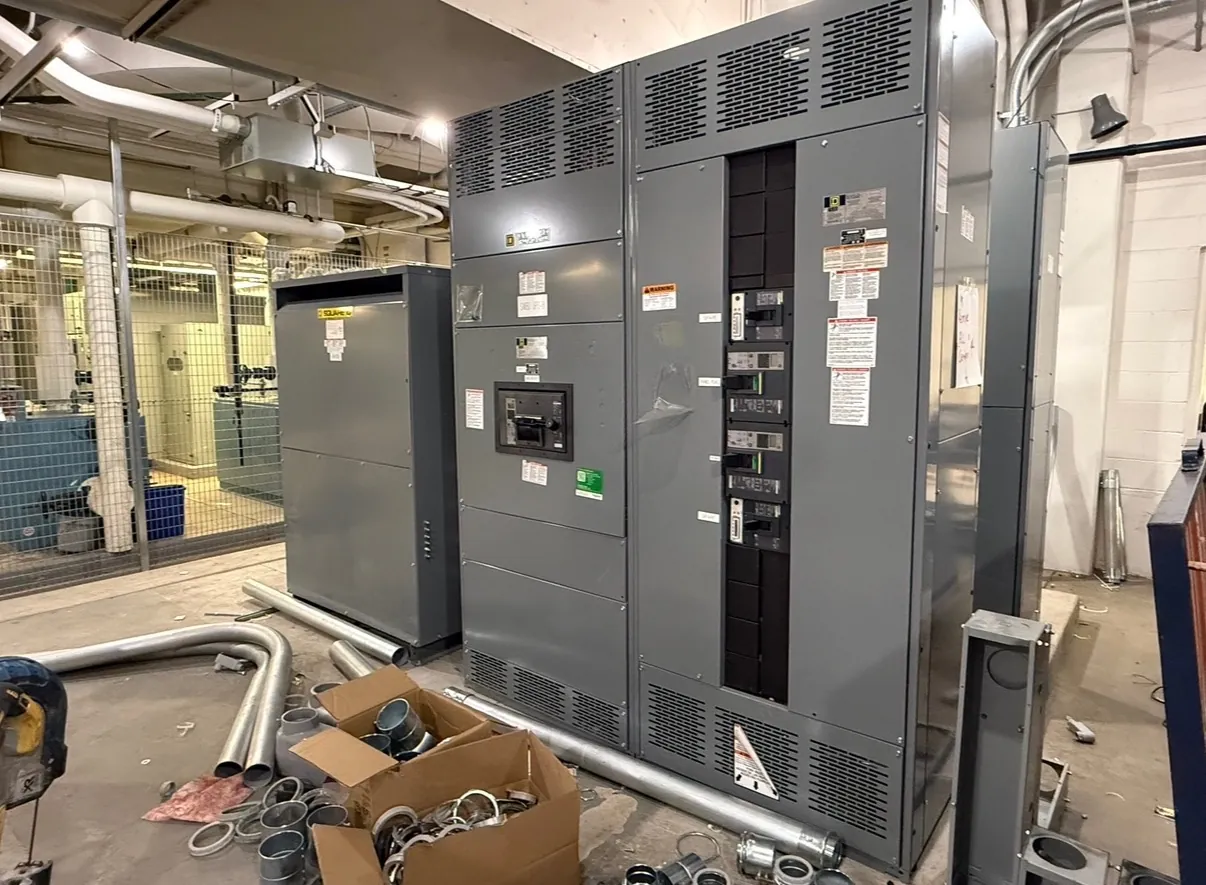
Data Center Switchgear Planning for Winnemucca, Nevada
Data center power distribution has to connect utility service, backup generation, uninterruptible power supply (UPS) systems and downstream loads in a configuration that matches the facility’s operating plan. For a Winnemucca project, switchgear and switchboard selections should follow the electrical design, not a generic redundancy label. The one-line diagram, load schedules, fault-current information and sequence of operation give the engineering team a basis for defining equipment sections, ratings and interfaces.
Redundant paths may be arranged to serve separate load groups, provide alternate sources, or support transfer between sources. Those choices affect bus arrangement, protective-device placement, separation of equipment and the way a failure or maintenance condition changes available capacity. Redundancy on paper is not enough if shared upstream equipment, controls or downstream connections create a common point of interruption. The design team should document normal and alternate operating states and identify which loads are expected to remain supplied in each state.
Coordinate Utility, Generator and UPS Interfaces
Switchgear at the service entrance may interface with utility equipment, while other sections connect generator sources, UPS input or bypass circuits, and distribution to critical loads. The exact boundaries depend on the project’s electrical architecture and the equipment furnished by other parties. Confirm who supplies and controls transfer equipment, where source conductors terminate, what status and control signals are exchanged, and which devices are included in each manufacturer’s scope.
Generator operating characteristics and UPS topology can influence protection and switching decisions. For example, available fault current can differ by source and operating mode, so protective-device performance should be reviewed across the conditions identified in the design. UPS maintenance or static bypass arrangements also need to be represented clearly in the one-line and sequence documents. Switchgear cannot establish a workable bypass plan by itself; the UPS, controls, interlocks and load-distribution design must be coordinated as a system.
Define a Maintainable Bypass Sequence
A bypass arrangement is useful only when its purpose, boundaries and operating states are understood. The project team should decide which equipment may be isolated for planned maintenance, what alternate path serves the load, and whether the bypass is intended for the UPS, a switchboard section or another defined portion of the distribution system. Those decisions shape device selection, bus connections, interlocking requirements and available space.
Review the sequence with the electrical engineer, UPS supplier, controls integrator and operations representatives before equipment details are finalized. Drawings should show the intended transitions and the conditions that prevent incompatible sources or paths from being connected. Equipment labeling, control interfaces and documentation should support the approved design. Operating procedures and switching decisions belong to the facility’s qualified personnel and engineering review; they should not be inferred from equipment descriptions alone.
Study Selective Coordination and Protection
Selective coordination is a system-level design objective: protective devices are evaluated so that a fault is isolated as close as practicable to its location while the rest of the intended system remains in service. The analysis requires the project’s fault-current data, protective-device selections and settings, conductor information, and relevant source configurations. Generator and UPS modes may affect the study, so reviewing only the normal utility condition can leave important operating cases unaddressed.
Device ratings and system voltage are related but distinct design details. Interrupting ratings, bus ratings and other equipment characteristics must suit the available fault current and project requirements at the installation point. Applicable product standards also depend on equipment type and construction; UL 891 applies to applicable low-voltage switchboards, not every product described as switchgear. Listings, ratings and construction details require confirmation for the specific proposed assembly and project.
Plan Winnemucca Receiving and Installation Logistics — Data Center Switchgear in Winnemucca, NV
Equipment delivery planning should account for the route from the receiving point to the electrical room, not just the site address. Confirm access roads, turning and staging areas, unloading equipment, door and corridor clearances, floor capacity, available laydown space and any restrictions on delivery timing. Site conditions and seasonal access can affect the receiving plan, but should be evaluated for the actual facility rather than assumed from the city’s location.
Section shipping limits also matter. The permitted section dimensions and weights depend on the design and transportation constraints; they should be established early enough to align with room access and the installation sequence. A project may need sections delivered in a particular order, staged securely, or moved through the building using a defined handling plan. Coordinate those requirements with the general contractor, electrical installer and equipment manufacturer before the final delivery schedule is set.
Prepare a Complete Switchgear Quotation Package — Data Center Switchgear in Winnemucca, NV
Useful quotation inputs include the one-line diagram, service and distribution voltage, system grounding, available fault current, load and feeder schedules, source and transfer requirements, specified ratings, enclosure requirements, and any project specifications or applicable listing requirements. Include the UPS and generator interface documents when available, along with the intended redundancy and bypass sequence. Clarify which devices, controls, metering, accessories and connections are furnished by others.
Also provide the electrical-room layout, cable-entry preferences, site access information, section shipping limits and target installation sequence. These details help identify design questions before manufacturing begins. A U.S. manufacturer building new custom equipment with all-American components can support a project’s domestic sourcing objectives and nationwide shipment, but final configuration, schedule and compliance details must be confirmed against the project documents. Winnemucca facility requirements and site conditions should be reviewed by the project’s qualified electrical professionals before equipment is released for manufacture.