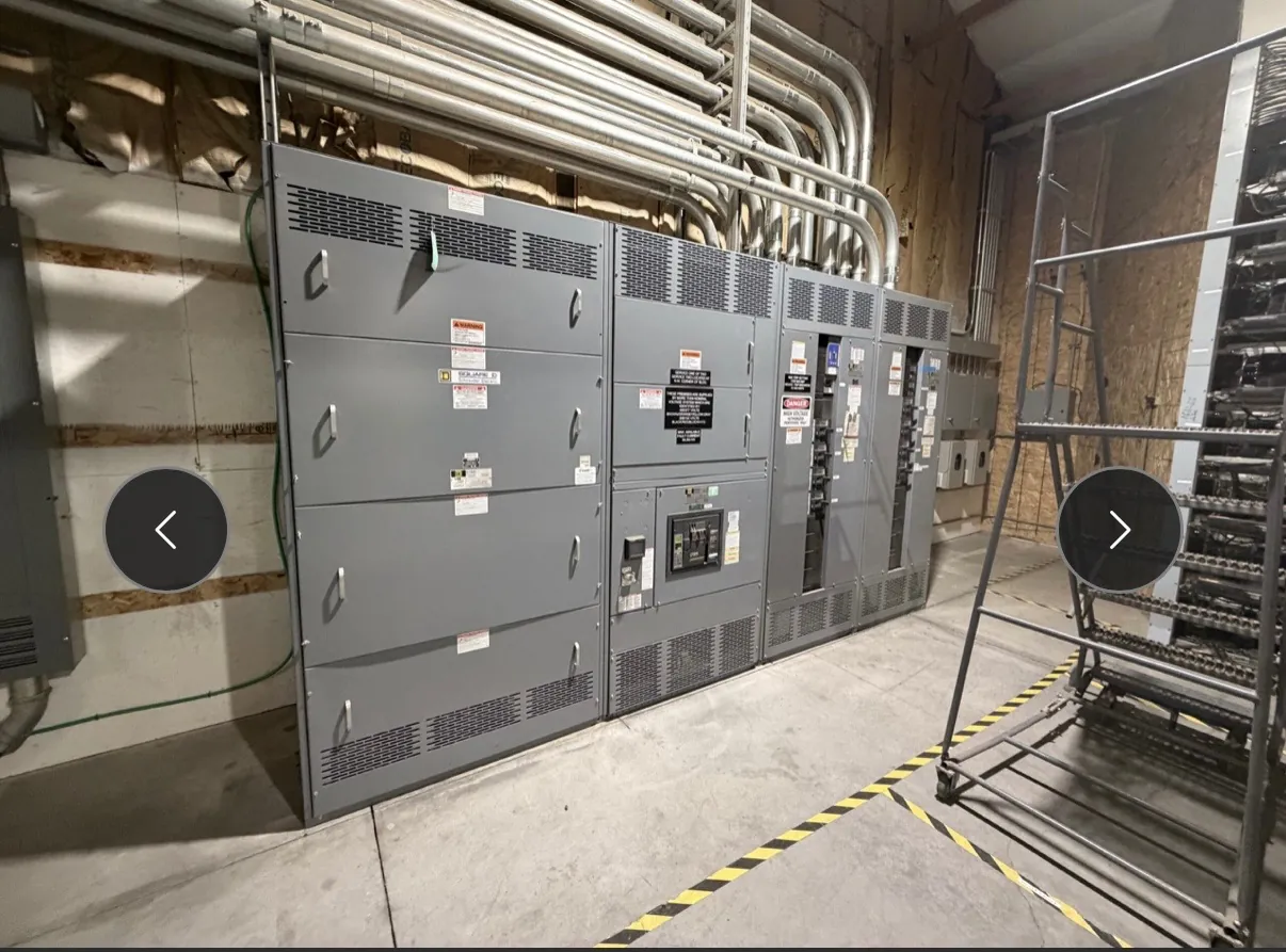
Automatic transfer switches for Sparks facilities
An automatic transfer switch (ATS) moves selected electrical loads between a normal source and an alternate source when the normal source no longer meets configured conditions. In a Sparks facility, that may mean transferring designated loads between utility service and an on-site generator, but the right arrangement depends on the building’s electrical design, required continuity, and available equipment. An ATS is not simply a switch sized to match a generator: its source-monitoring logic, load rating, fault withstand capability, neutral arrangement, and relationship to protective devices all need to suit the installation.
We manufacture new custom power-distribution equipment in the United States using all-American components, with short lead times and nationwide shipping. For Sparks projects, equipment configuration and shipping arrangements can be discussed during quotation; site conditions and project requirements still determine the final design. We do not assume a particular utility service, generator arrangement, or facility type without project information.
Choose the transition behavior around the load
Transfer transition describes how the ATS changes connections from one source to another. Open-transition equipment disconnects one source before connecting the other, creating a brief interruption. That break is acceptable for many loads, but even a short interruption can affect sensitive controls, process equipment, or systems that need continuous operation. Closed-transition equipment briefly connects sources together during transfer under conditions intended for that operating mode. It can reduce interruption, but requires careful review of source compatibility, controls, protection, and whether paralleling is permitted by the system design and applicable requirements.
Delayed-transition arrangements hold the load disconnected for a set interval before connecting the alternate source. This can give residual voltage from certain motor loads time to decay, depending on the application and engineered settings. The correct choice is not determined by a general preference for faster transfer; engineers should evaluate load behavior, source characteristics, operating sequence, and the consequences of an interruption.
Source sensing and transfer controls must reflect operating needs
An ATS monitors source conditions and responds according to its control logic. Sensing may include voltage and frequency conditions, phase-related conditions, and programmed time delays. Those settings influence when the switch recognizes an unacceptable normal source, when it commands a transfer, and how it responds when normal power returns. Generator start signaling and the timing of transfer and retransfer are also part of the interface.
For quotation, identify the normal and alternate sources, the intended transfer sequence, and any required control or status interfaces. Note whether the project calls for remote indication, generator controls, building-management connections, or other specified signals. These details help define a suitable control package, but final settings should be established by qualified project professionals after review of the actual sources and loads.
Load rating and fault withstand are different considerations
The ATS load rating must be appropriate for the load it carries and the conditions of the installation. Connected load, expected operating duty, motor starting, and the way loads are grouped can affect equipment selection. A switch’s current rating is not the same thing as system voltage, and neither value alone establishes that the equipment can withstand or interrupt the available fault conditions.
For a Sparks project, obtain the available fault current at the proposed connection point and provide it with the system information used for equipment selection. The ATS withstand and closing capability must be suitable for that fault exposure in coordination with the specified protective device. Protective-device type and characteristics, upstream settings, and downstream loads need to be reviewed together; a rating or coordination conclusion cannot be selected responsibly from a city name or nominal voltage alone.
Neutral switching depends on the source and grounding design
Whether the ATS switches the neutral is an application-specific design decision. It can depend on how the alternate source is grounded, how the system neutral is arranged, and how the project treats separately derived sources and ground-fault protection. A switched-neutral configuration and a solid-neutral configuration are not interchangeable options to choose solely by habit. Incorrect assumptions can affect grounding paths, sensing, and protective-device coordination.
Provide the engineer’s grounding and bonding concept, source configuration, and relevant protective scheme for review. The equipment design should follow the project’s engineered system and applicable requirements, rather than presume that every generator or facility needs the same neutral arrangement.
UL 1008 and project documentation
UL 1008 applies to transfer-switch equipment where required by the product scope and project requirements. It is distinct from standards that apply to other kinds of distribution equipment, and it should not be treated as a blanket statement that every assembly or installation is listed or approved. Confirm the required product scope, ratings, listing needs, and project specifications during engineering and quotation. Applicable requirements and acceptance criteria may depend on the authority having jurisdiction and the installation.
Information that supports a Sparks quotation
A useful request includes the one-line diagram, system voltage and phase, normal and alternate source details, requested ATS load rating, available fault current at the connection point, protective-device information, and the intended transition type. Include the load schedule or load characteristics, neutral and grounding requirements, control interfaces, enclosure and installation conditions, and any specified standards or listing requirements. For a Nevada site, note where the equipment will be installed and any access, environmental, or coordination constraints that could affect enclosure selection or delivery planning. Engineers must confirm the final design against site conditions and applicable requirements. Clear inputs make it easier to develop a new manufactured assembly that fits the project rather than relying on assumptions.