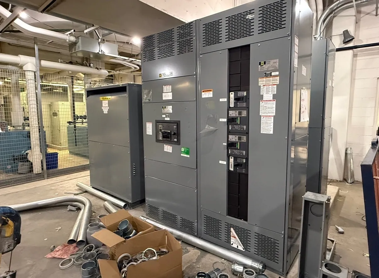
Pad-Mounted Switchgear for Reno Outdoor Installations
Pad-mounted switchgear places switching and distribution equipment in a weather-resistant enclosure at ground level, often where a project needs an outdoor interface between utility service and a facility’s electrical system. In Reno, equipment selection should reflect the actual site—not simply the city name. Elevation, seasonal temperature conditions, wind and snow exposure, drainage, available working space, and the route for incoming and outgoing cables can all affect enclosure, foundation, and rating requirements. Each project’s design criteria should be checked against the equipment’s documented ratings and configuration.
We manufacture new custom power-distribution equipment in the United States using all-American components. For a Reno project, the design discussion begins with the one-line diagram, service arrangement, load requirements, and utility interface. Those details help establish whether a proposed pad-mounted assembly is appropriate and what switching functions, protective devices, compartments, and connections need to be considered. Equipment and project requirements must be reviewed by qualified electrical professionals; a product description alone cannot establish suitability for a particular installation.
Enclosure, Site Exposure, and Environmental Protection
The enclosure must suit the installation environment as well as the electrical arrangement inside it. Specify the intended location, exposure to precipitation and blowing dust, potential snow accumulation, drainage conditions, and nearby traffic or landscaping. The project team should confirm how doors, barriers, compartments, and access points align with the site layout and applicable requirements. Environmental protection depends on the equipment design and installation details, so enclosure features should be confirmed for the actual application rather than assumed from the term “pad-mounted.”
Reno-area elevation and ambient-temperature design criteria deserve particular attention. Confirm the installation altitude and the temperature range used for design, then compare them with the manufacturer’s applicable equipment ratings and limitations. Do not infer that a standard configuration meets a site’s environmental criteria without review. If conditions differ from the basis of design, the engineer and manufacturer can evaluate what adjustments or documentation are needed.
Foundation, Clearances, and Cable Entry
A pad is not just a support surface: its dimensions, elevation, anchoring provisions, access openings, and relationship to finished grade affect the installation. Foundation plans should be coordinated with the enclosure footprint and the locations of cable compartments and conduits. Drainage and water management matter; the finished site should not direct runoff into equipment openings or leave access obstructed by standing water, paving, or accumulated material. Civil and electrical plans should agree before foundation work proceeds.
Plan cable entry around the actual feeder arrangement, conductor requirements, bend space, and termination provisions. The entry path may be from below the pad, but the appropriate configuration depends on the equipment design and project drawings. Confirm conduit locations and sizes, phase arrangement, grounding provisions, and the separation of incoming and outgoing circuits with the responsible electrical designer. Changes made after a pad or conduits are installed can create costly coordination issues, so the approved equipment outline and connection details should be reviewed early.
Utility Interface and Switching Configuration
Utility requirements are specific to the serving utility and service arrangement. Identify the point of connection, ownership boundaries, required switching functions, metering or protection interfaces, and any utility-provided design criteria. The utility interface must be coordinated with the facility’s distribution scheme; neither a generic equipment configuration nor a citywide assumption can establish acceptance. Utility review and approval, where required, are separate from manufacturing and must be confirmed by the project team.
Switching and protective-device choices should follow the one-line diagram and the engineer’s coordination study. Define the intended circuit arrangement and operational purpose of each way, along with the required interconnections and control interfaces. Avoid specifying a device solely by a familiar name: its function, electrical rating, and compatibility with the rest of the system need to be verified together.
Ratings, System Voltage, and Project Review
Provide the nominal system voltage and the required equipment ratings as distinct pieces of information. A voltage description does not, by itself, establish the interrupting, short-circuit, continuous-current, or other ratings needed for an assembly. Those values depend on the system study, source characteristics, protective coordination, and applicable design requirements. Listings and standards also apply only to the products and configurations they cover; they should not be assumed for every pad-mounted assembly.
For an accurate quotation, share the one-line diagram, site and foundation information, cable-entry plan, utility criteria, environmental design basis, desired switching arrangement, and any applicable project specifications. Include confirmed altitude and ambient-temperature criteria, and identify which requirements remain subject to engineering or utility review. Complete inputs help clarify scope and reduce avoidable drawing revisions.
Manufacturing and Shipment to Reno
Custom equipment is developed around the approved project requirements, with design details coordinated before release for manufacture. Drawing review should resolve enclosure dimensions, conduit positions, interfaces, and equipment ratings before related site work is finalized. Our assemblies are built in the USA with all-American components, support short lead times, and can ship nationwide, including to Nevada. Shipment planning should account for site access, unloading arrangements, and the sequence of foundation and electrical work; timing and delivery details are confirmed for each order.