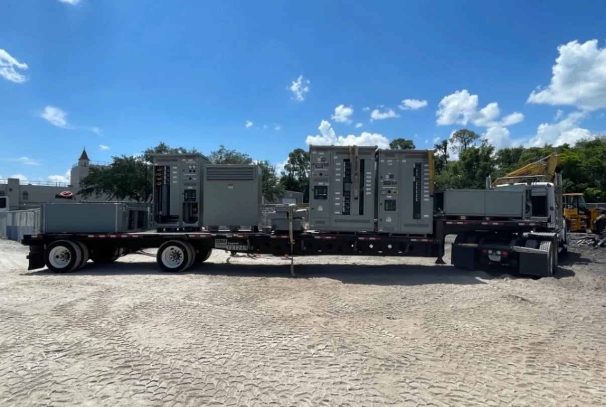
Motor Control Centers for Reno, NV Projects
Reno-area facilities use motor control centers (MCCs) to organize motor starters, variable-frequency drives (VFDs), feeder protection and related controls in a coordinated assembly. The right configuration depends on the connected motors and loads, the electrical system, the installation environment and how operators and maintenance teams need to access the equipment. A useful specification starts with the project’s one-line diagram and equipment schedule—not simply a requested enclosure size or a single rating.
We manufacture new custom power-distribution equipment in the United States using all-American components, with short lead times as a manufacturing goal and shipment available nationwide, including to Nevada. Actual configuration, ratings, schedule and shipping arrangements depend on the project and require confirmation. For a Reno installation, the site conditions and electrical design should be reviewed before equipment details are finalized.
Starter and VFD Sections Need Load-Specific Design
Across-the-line starters, reduced-voltage starting arrangements and VFD sections serve different operating needs. Starter selection depends on motor nameplate information, starting method, operating frequency, control scheme and the way the driven load behaves during startup. For VFDs, the design team should identify which motors require speed control, how commands and status signals will interface with the facility controls, and whether drive-related requirements affect the assembly layout or heat management.
VFD integration also calls for attention to the interface between the drive, motor and upstream electrical system. Project engineers should review drive input requirements, protective-device coordination, grounding and control wiring as applicable. A drive’s presence does not by itself establish the correct feeder or short-circuit rating for the complete MCC. Those decisions require review of system data and the selected equipment configuration.
Short-Circuit Ratings and Feeder Protection Must Coordinate
Specify the available fault current at the MCC location and the system voltage, along with the project’s required short-circuit rating. These are related design inputs, but they are not interchangeable: a short-circuit rating describes equipment performance under defined conditions, while system voltage describes the electrical system. The engineer must confirm that the selected rating is suitable for the installation and that the proposed combination of components is supported for the intended configuration.
Feeder protection should be coordinated with the upstream distribution equipment and downstream motor circuits. The design review may consider protective-device types and settings, conductor information, motor starting behavior and the facility’s coordination objectives. Avoid treating a catalog value or a preliminary schedule as a final determination. The responsible electrical engineer should verify the available fault current, system conditions and protection approach using project-specific information.
Confirm Whether UL 845 Applies to the MCC
For a Reno project, ask the electrical engineer, owner and specification team whether UL 845 is required for the motor control center and what documentation or evaluation the project requires. UL 845 is the relevant standard to check for MCC applications; it should not be assumed that every assembly, configuration or project has the same listing requirement. UL 891 applies to applicable low-voltage switchboards and should not be presented as a general MCC standard.
State the required listing or standard in the inquiry and identify any project specifications that govern construction, labeling or submittals. The applicable product scope, selected components and final configuration must be confirmed rather than inferred from a general product description. Listing status, ratings and project acceptance requirements should be established for the specific equipment being quoted.
Reno Site Conditions Affect Equipment Selection
Reno’s elevation makes installation altitude a project input worth checking, but no site condition should be assumed from the city name alone. Confirm the actual installation altitude and compare it with the equipment ratings and the applicable design criteria. Likewise, provide the expected ambient-temperature conditions for the equipment location. Temperature and altitude considerations can affect the suitability of an assembly or its components, so the project engineer and manufacturer should review the actual criteria before the design is settled.
Also describe whether the MCC will be installed indoors or outdoors, the available space, environmental exposure and cable-entry constraints. These details influence enclosure selection, section arrangement, ventilation considerations and field connections. A Nevada shipping destination does not establish the conditions at the final installation point.
Plan Access, Interfaces and Quote Inputs Early
Maintenance access should be considered during layout, not left to the end of the specification. Provide the intended working area, cable approach, access direction and any room or egress constraints. The design team can then review section placement and service access against the facility layout. Do not assume that a particular arrangement is appropriate without a site and design review.
For a useful quotation, provide the one-line diagram, load and motor schedule, system voltage, available fault-current information, requested short-circuit rating, feeder-protection requirements, control and VFD interfaces, installation environment, altitude and ambient-temperature criteria, and any UL 845 or project-specification requirements. Include delivery destination and schedule needs for shipment to Reno. These inputs help define a buildable scope; final equipment ratings, listing details, coordination and suitability remain subject to qualified engineering review and confirmation.