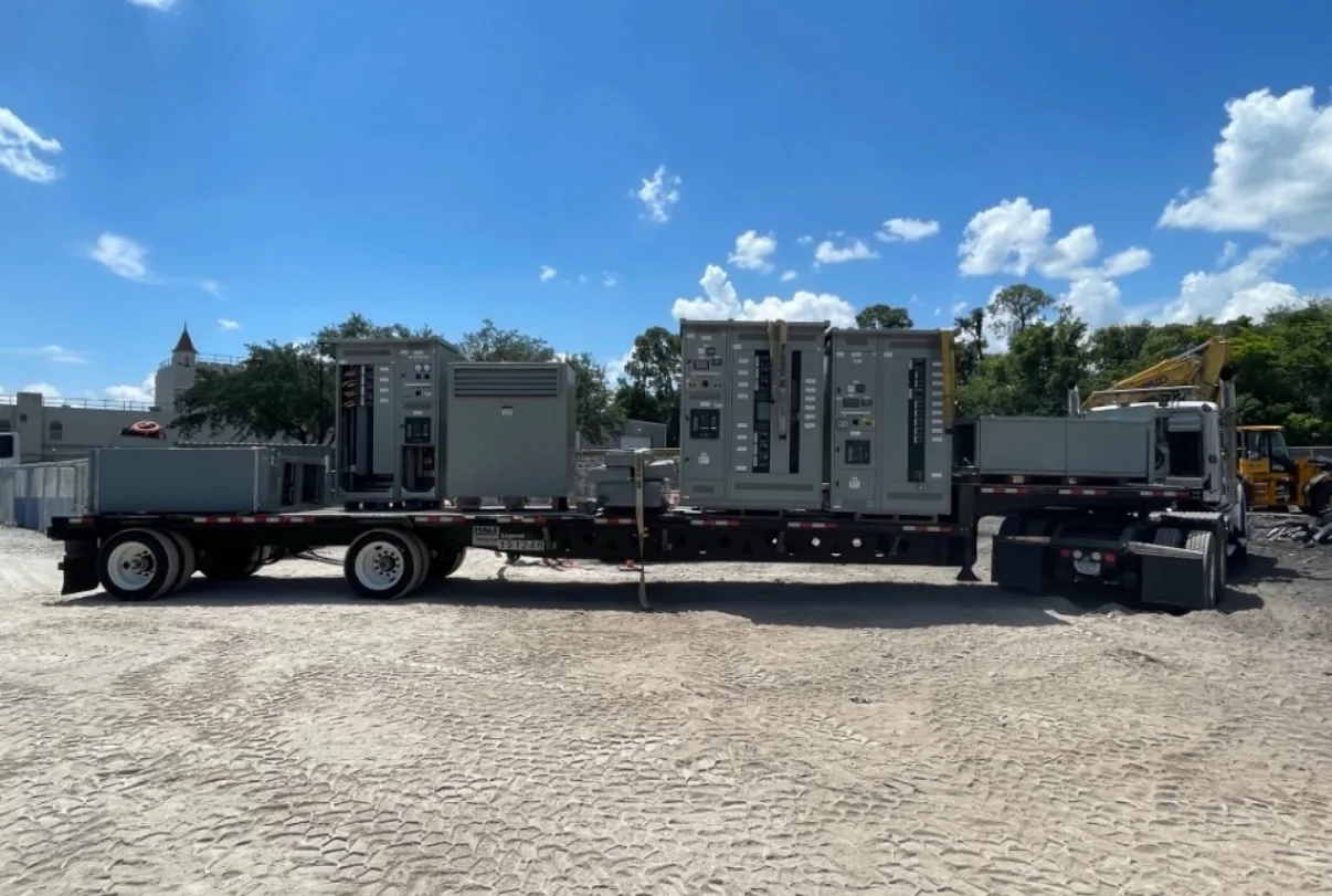
Pad-Mounted Switchgear for Pahrump, NV Projects
Pad-mounted switchgear provides an outdoor point for switching and, depending on the design, protecting or isolating portions of a distribution system. In Pahrump, the right assembly depends on the electrical service and the site around it—not simply on selecting an enclosure by voltage. Project planning should establish the service voltage, grounding approach and available short-circuit current at the proposed location. Those details guide equipment selection and must be confirmed by the project’s qualified electrical engineer and the serving utility where applicable.
Custom pad-mounted switchgear can be configured for a project’s stated requirements, with new equipment manufactured in the United States using all-American components. The assembly’s arrangement, ratings and interfaces still require review against the one-line diagram, utility requirements and site conditions. Shipping to Pahrump can be coordinated as part of the project, but access, unloading and placement need to be considered separately from equipment design.
Enclosure Placement, Access and Environmental Protection
The enclosure location affects both installation and future access. Confirm required working and operating clearances, door swing, approach routes, and separation from walls, vehicle paths, landscaping and other site features. A location that looks convenient on a plan may be difficult to reach with installation equipment or may conflict with drainage and pedestrian circulation.
Outdoor enclosures are intended for exterior service, but the specified construction must match the exposure and maintenance expectations for the actual site. Discuss precipitation, dust, sun exposure, temperature conditions, potential impact and corrosion concerns with the design team. Enclosure finish, hardware, barriers and access provisions should be stated in the project documents rather than assumed. Environmental protection also depends on correct installation and on maintaining the enclosure’s designed openings, seals and closures.
Foundation and Cable-Entry Coordination
The pad is part of the equipment interface. Its dimensions, elevation, flatness, anchorage and openings should be coordinated with the manufacturer’s approved equipment drawings and the civil and electrical plans. A concrete foundation that is designed before cable-entry locations are settled can create avoidable field conflicts. Confirm conduit routes and entry points early, including their orientation and space for conductors, terminations and bending requirements.
Underground cable entry is common for pad-mounted installations, but the exact arrangement depends on the switchgear configuration and project design. Identify incoming and outgoing circuits, phase arrangement, conductor type and size, termination requirements, and any provisions for spare conduits. The electrical engineer should verify conductor and termination compatibility; the manufacturer’s drawings should then be checked against the foundation and conduit plan before concrete work proceeds.
Utility Interfaces and System Grounding
Utility-facing equipment may need to conform to requirements for incoming connections, switching functions, compartment arrangement, access control or metering interfaces. These requirements vary by serving utility and service arrangement. Obtain the utility’s current project-specific criteria and identify which party supplies, installs and connects each interface. Do not rely on a generic configuration to establish acceptance for a particular service.
Grounding must be evaluated as part of the complete installation, not treated as an enclosure detail alone. The project team should define the grounding approach, bonding points and connection requirements in coordination with the utility and qualified electrical engineer. For a Pahrump site, verify those details alongside service voltage and available short-circuit current; site conditions and the distribution system determine the applicable design decisions.
Ratings, Switching Arrangement and Coordination
Equipment ratings are not interchangeable with system voltage. The specified voltage class, continuous-current rating, interrupting or fault-duty capability, and switching functions must each suit the system and the intended application. The available short-circuit current at the installation point is especially important when evaluating fault-duty requirements. Confirm the values and their basis with the electrical engineer and utility, then match them to the proposed equipment documentation.
Also define the number and function of ways, circuit positions, operating devices, protective components and any monitoring or control interfaces required by the one-line diagram. Protection and coordination depend on the wider system, including upstream and downstream devices and the project’s fault and load information. A switchgear quotation cannot replace that engineering analysis. Listings, ratings and any applicable standards are specific to the proposed equipment and configuration and should be confirmed rather than presumed.
Information to Prepare for a Pahrump Quotation
A useful request for quotation includes the one-line diagram, service voltage, grounding information, available short-circuit current, required equipment ratings, switching arrangement and utility criteria. Include site plans or foundation details, cable-entry drawings, conductor and termination data, environmental considerations, and any required controls or accessories. Note delivery access and the planned installation sequence so shipping and site coordination can be discussed without assuming a delivery date.
With those inputs, the equipment design can be reviewed against the project’s electrical, civil and utility interfaces before fabrication. The manufacturer can supply new custom-built equipment for projects in Pahrump and ship nationwide. Final configuration, ratings and any listing claims must be confirmed for the specific assembly and reviewed by qualified project professionals.