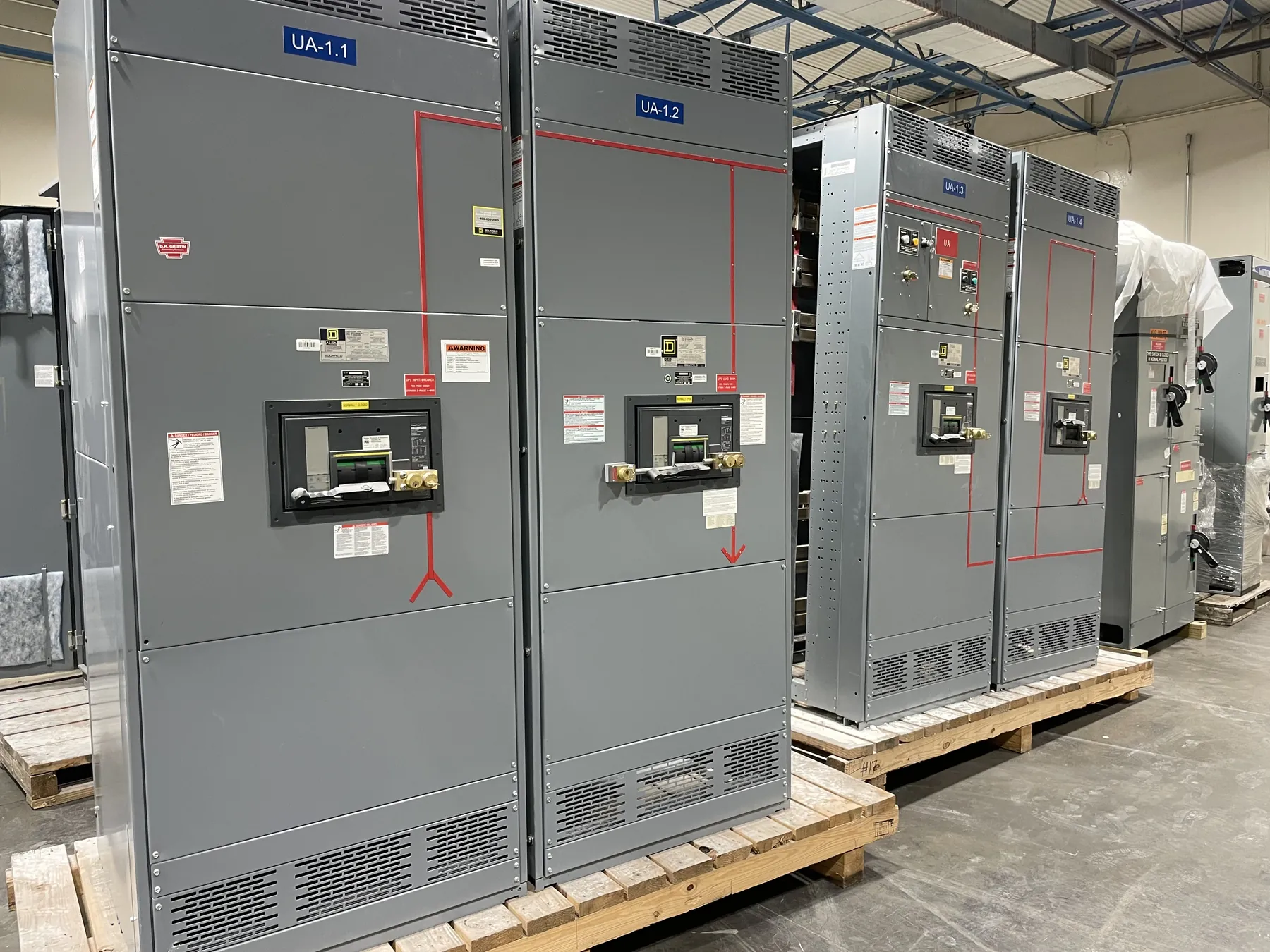
Commercial Switchgear Planning for North Las Vegas Buildings
Commercial electrical distribution in North Las Vegas must fit the building’s service arrangement, tenant layout and operating plans—not just the available electrical-room footprint. A switchboard lineup may need to serve common areas, individual tenant spaces, mechanical equipment and future alterations, with each load group accounted for in the distribution plan. Early coordination helps avoid a layout that accommodates the equipment but leaves little room for cable routes, access or later work.
Our U.S. manufacturing team builds new custom power-distribution equipment using all-American components and ships nationwide, including to North Las Vegas. Equipment configuration depends on project documents and qualified engineering review. Product ratings, applicable listings and project-specific details must be confirmed for the intended application; no single configuration suits every commercial service.
Arrange Tenant Feeders and Metering Around the Service Plan
Tenant feeders should be coordinated with the electrical design, lease boundaries, anticipated tenant loads and the building’s metering approach. Depending on the project, distribution may need separate sections or designated feeder provisions for tenant spaces, landlord loads and shared services. The design team should establish which circuits require individual metering, where metering equipment belongs, and how service personnel will access it.
Metering requirements can involve the serving utility, the owner’s operating practices and the project’s electrical design. Confirm the intended meter type and location, required interfaces, and any utility review before fixing the switchgear arrangement. Do not assume that a particular metering layout or equipment listing will meet utility requirements without project-specific confirmation.
Coordinate Incoming Service, Outgoing Cables and Utility Interfaces
Before lineup dimensions are settled, map the incoming service route and every major outgoing cable route. The service entrance may approach from above, below or another direction determined by the building and site design. Feeder exits also need space for bends, transitions and access to connected equipment. These paths can affect section placement, cable-entry provisions and the amount of room required around the lineup.
Document the service source, system voltage, available fault-current information when established by the project team, protective-device requirements and utility interface. A switchgear rating is not the same thing as system voltage; the equipment ratings and configuration must be evaluated against the actual system and design conditions. The electrical engineer and utility should resolve service details and approvals rather than relying on assumptions during quotation.
Balance Future Capacity With Present Loads and Space
Commercial tenants and building uses can change, so owners may want spare feeder provisions or room for anticipated distribution changes. That flexibility has tradeoffs: additional sections or reserved space can affect lineup length, room layout, cable routing and initial project scope. Conversely, a tightly constrained arrangement may leave limited options for later changes. Identify which future loads are reasonably anticipated and distinguish them from general contingencies so the design can reflect a useful plan.
Load schedules, feeder quantities, breaker requirements and the intended distribution arrangement give the design team a basis for evaluating capacity. Do not treat an unassigned space or spare provision as a guarantee that any future load can be added. Future changes still require engineering review of the equipment, conductors, protection and system conditions.
Set Working Clearances and Delivery Access Before Final Dimensions
Room planning must account for the applicable working space, equipment access, door swing, nearby walls and other installed services. Required clearances depend on the equipment and installation conditions and should be determined by qualified professionals using the project’s applicable code requirements. Show those dimensions on coordinated drawings; a nominal equipment footprint alone does not establish that the installation will fit or remain accessible.
Delivery access deserves the same early attention. Confirm the route from the receiving point to the electrical room, including openings, turns, thresholds, staging space and any restrictions on moving equipment. For a North Las Vegas site, the project team should verify actual site access and facility conditions rather than assume that a truck can reach the room or that a lineup can be moved through the planned route. These checks may influence how the equipment is arranged and delivered.
Prepare a Useful Commercial Switchgear Quotation Package — Commercial Switchgear in North Las Vegas, NV
A focused quotation package helps align the proposed lineup with the project instead of relying on a generic description. Provide available one-line diagrams, load and feeder schedules, service information, preferred metering arrangement, room and access drawings, cable-entry direction, protective-device requirements and the project schedule. Note which details are confirmed and which remain subject to engineering or utility review.
UL 891 may apply to low-voltage switchboards when appropriate to the specified product and application; it should not be read as covering all switchgear or every project requirement. Confirm the applicable product scope, ratings and listing status for the equipment being considered. With coordinated inputs, the team can evaluate tenant distribution, future provisions, clearances and cable routes together, then develop a custom configuration for the North Las Vegas project without assuming unverified site or utility conditions.