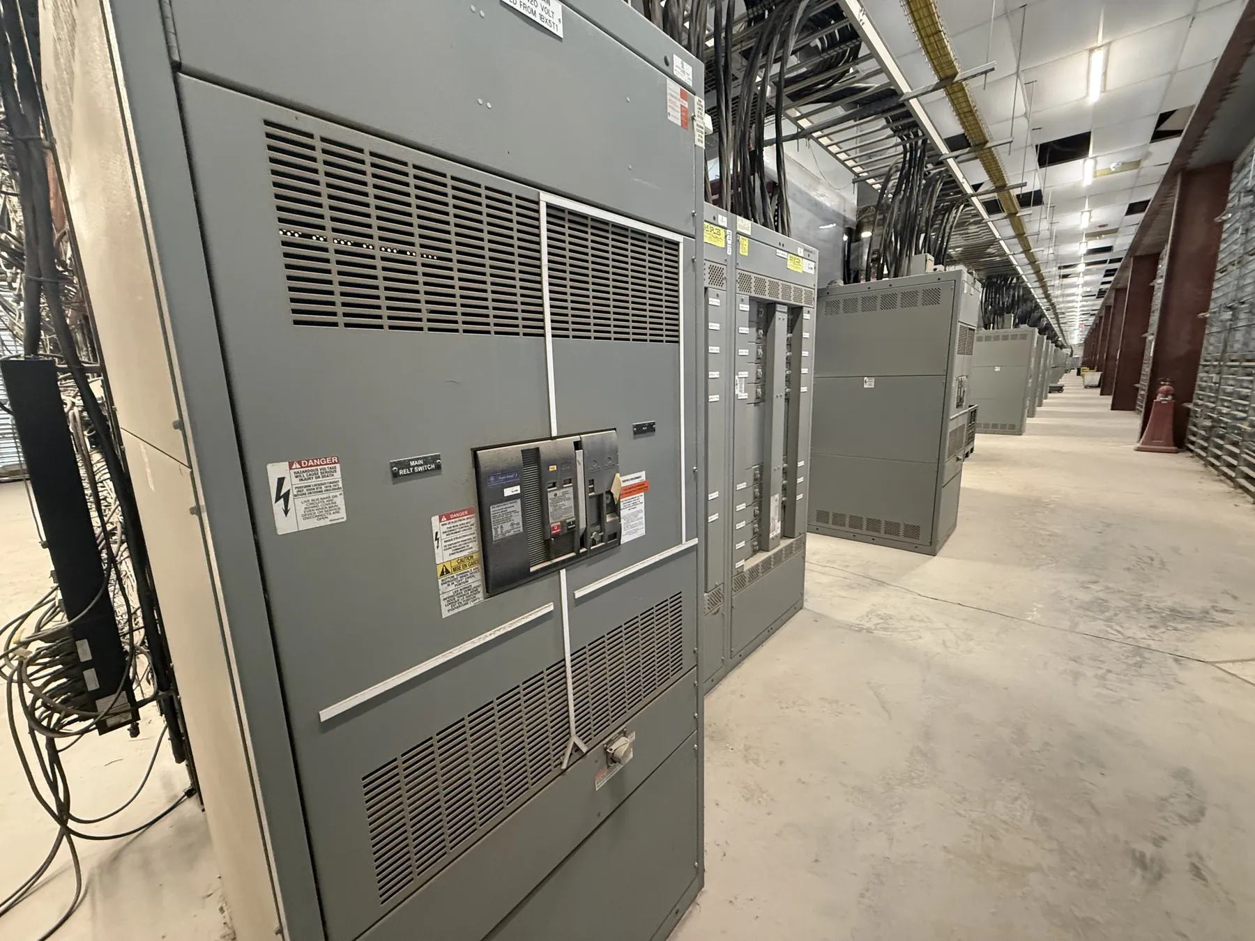
Commercial Switchgear for Tenant and Building Distribution
Commercial switchgear sits at the intersection of utility service, building operations, tenant needs and future changes to a property. A well-planned assembly does more than deliver power: it organizes incoming service, distribution sections, tenant feeders and metering in a way that supports the intended operating arrangement. For an office building, retail property, mixed-use development or other commercial facility, the right configuration depends on the service design and how the building is divided, occupied and maintained.
We manufacture new custom switchgear and power-distribution equipment in the United States using all-American components. Our work can be configured around a project’s documented requirements, with short lead times supported where the design and production schedule allow. Equipment ships nationwide, including to Nevada. The project team should confirm the application, ratings, listing needs and schedule before design and quotation are finalized.
Arrange Tenant Feeders, Sections and Metering Together
Tenant distribution is not simply a matter of assigning one feeder to each lease space. A designer may need to account for tenant count, load characteristics, anticipated subdivision or combination of spaces, and the location of downstream distribution equipment. These decisions affect feeder quantities and sizes, section layouts, cable entry and termination space, and the relationship between the main service equipment and tenant panels.
Metering arrangements also need early coordination. The project should identify whether metering is provided at the switchgear, at downstream panels, or through another specified arrangement, and who supplies and integrates any metering components. The serving utility’s requirements, the building’s billing plan and the electrical design all matter. Metering provisions should not be assumed to satisfy utility requirements without review by the project engineer and utility representatives.
Coordinate Utility Service and System Ratings
The incoming service is a defining interface. Quotation and design inputs should establish the documented system voltage, phase and wire arrangement, available fault-current information when provided, service entrance configuration, and the utility’s connection and metering requirements. The equipment rating is not interchangeable with the system voltage: voltage, current, short-circuit or withstand ratings, and other applicable characteristics must be specified and checked for the actual installation.
Where a project uses low-voltage switchboards, UL 891 may be relevant to the specified product. It should not be treated as a blanket standard for every type of switchgear or as proof that an unspecified assembly is listed. The applicable construction, ratings and listing requirements depend on the equipment and project. A qualified electrical engineer should coordinate the one-line diagram, protective-device requirements and site conditions, with utility input where necessary.
Plan for Future Capacity Without Overbuilding
Commercial owners often want room for tenant turnover, added equipment or later building improvements. Future capacity can be addressed through planned spaces, spare feeder provisions or a distribution arrangement that supports anticipated changes. Each option has tradeoffs: unused provisions can add cost and occupy valuable enclosure space, while a tightly specified layout may limit later flexibility. The useful question is not whether to “build in extra” generally, but which credible future loads or tenant changes the design should accommodate.
Capacity planning must consider the complete electrical system, not just open breaker positions. The engineer needs to evaluate service capacity, bus and feeder ratings, protective-device coordination, available fault current and downstream equipment. A spare way does not by itself establish that the service can support a future load. Changes in tenant use or equipment can also require updated load calculations and review of the existing distribution system.
Fit Equipment to the Electrical Room and Work Clearances
Switchgear dimensions and section arrangement should be coordinated with the electrical room before release. Relevant details include available wall and floor space, doorways and access routes, structural constraints, cable entry direction, termination access, environmental conditions and the location of adjacent equipment. A layout that appears to fit on a plan may still create installation or maintenance conflicts if doors, working space or cable routes are not considered together.
Required working clearances and access provisions depend on the installation, equipment and applicable electrical requirements. They should be established by the project’s qualified design team using site information, rather than inferred from a product outline. In Nevada, shipping and site logistics should be planned around the receiving location, unloading arrangements and access to the electrical room. Building conditions vary; no local facility condition or delivery arrangement should be assumed in advance.
Prepare a Clear Commercial Switchgear Quotation Package
A useful inquiry typically includes the one-line diagram, equipment schedule, documented system and rating requirements, feeder and metering schedule, utility criteria, preferred enclosure and cable-entry details, and available electrical-room plans. Note the required listing or construction standard, if specified, and identify any known future provisions. If documents are preliminary, say so; unresolved inputs can affect the proposed configuration, price and production schedule.
Our engineering and manufacturing process uses the project documents to define the assembly and identify questions requiring resolution before fabrication. The customer’s engineer remains responsible for system design and site-specific decisions, including protection, coordination, code compliance and clearances. Confirming those interfaces early helps produce commercial switchgear that aligns with the building’s distribution plan and the practical limits of its installation.