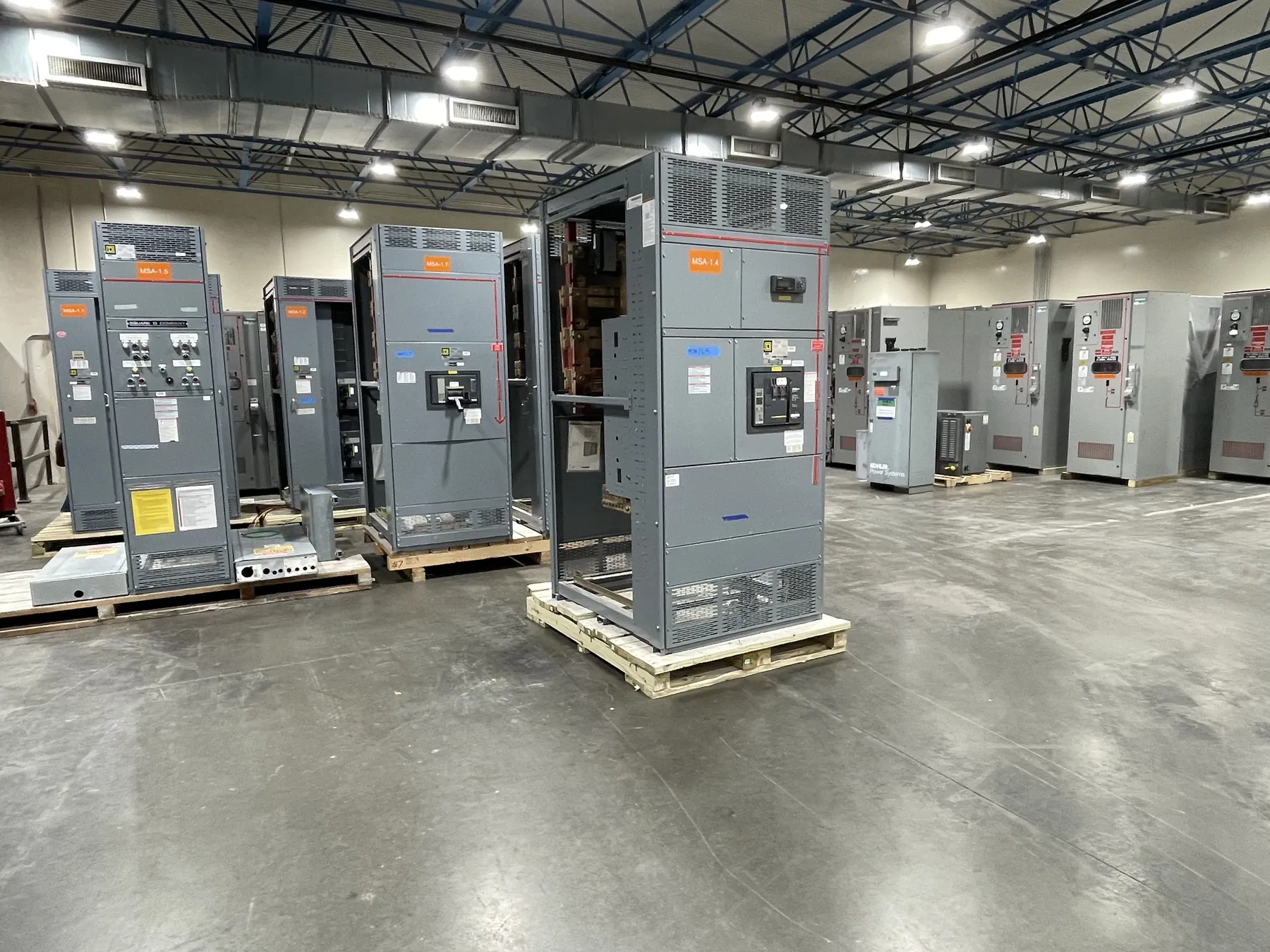
Service Entrance Switchboards for Lovock Projects
A service entrance switchboard is the point where a facility’s incoming electrical service is received, metered and distributed downstream. For a Lovelock project, its layout needs to reflect the serving utility’s requirements, the facility’s electrical design and the responsibilities of the owner, electrical contractor and commissioning team. Those details should be settled before the service section is finalized; a switchboard quote alone cannot establish the permitted service arrangement.
Start by confirming the service configuration and the intended role of the switchboard. The design team should identify the system voltage, phase and wire arrangement, service rating, incoming conductor approach and downstream distribution plan. A product’s current rating is not the same as system voltage, and neither should be inferred from a general description. The equipment design, available fault current, required markings and applicable approvals all need project-specific review.
Resolve Metering and Utility Interfaces Early — Service Entrance Switchboards in Lovelock, NV
Utility metering can affect the service section’s dimensions, compartment arrangement, access and coordination with the incoming service conductors. Confirm whether the utility specifies a particular metering arrangement, who furnishes the metering components, and which party is responsible for the meter enclosure or related provisions. Requirements can vary, so assumptions based on another site or utility territory may not apply in Lovelock.
Document the utility’s interface requirements for the project team and equipment manufacturer. These may include the point of connection, metering location, equipment access expectations and review or approval steps. The utility’s acceptance of an arrangement is separate from the equipment manufacturer’s design review and any applicable authority approvals. Allow time for each review in the project schedule, and resolve comments before production details are released.
Coordinate the Main Disconnect and Service Section — Service Entrance Switchboards in Lovelock, NV
The main disconnect arrangement should match the electrical engineer’s one-line diagram and the intended distribution topology. Confirm the number and type of service disconnects, their placement, the relationship to distribution sections, and whether future expansion or dedicated feeders affect the lineup. The approved design must also address applicable code requirements and the authority having jurisdiction’s interpretation; these decisions should not be left to a catalog description.
Available fault current is a key input to equipment selection and evaluation. Provide the project’s documented value and the information needed to establish the required short-circuit rating for the assembly and its components. Do not treat a switchboard’s current rating as evidence that it is suitable for the site’s fault-current conditions. A qualified engineer must review the system study, protective-device coordination and equipment ratings together.
Grounding, Bonding and Feeder Planning
Service grounding and bonding provisions depend on the service configuration and the governing electrical design. The team should clarify where the service bonding point is intended to be, how grounding connections are to be accommodated, and which components or conductors are by others. The manufacturer can use approved design documents to coordinate the equipment layout, but it cannot determine site grounding conditions or substitute for engineering review.
List every required outgoing feeder, including quantity, intended function, conductor entry direction and any known termination constraints. Feeder count and breaker or switch arrangements influence section space, bus configuration and access. Also identify spare provisions, if required, without assuming that unused spaces automatically provide a future-ready solution. Changes to feeder quantities after layout approval can affect the design and schedule, so reconcile the equipment schedule with the one-line diagram before quotation or release.
Prepare a Complete Lovelock Project Quotation Package
A useful quotation request includes the one-line diagram, load and feeder schedules, service and system ratings, documented available fault current, utility metering criteria, site conditions and requested delivery point. Share the required service entrance configuration, enclosure and access expectations, cable entry direction, and any known dimensional or handling limits. Identify which items are within the manufacturer’s scope and which will be supplied or completed by the contractor, utility or others.
For Lovelock delivery, confirm receiving hours, unloading equipment, access route, staging area and any restrictions on truck size or delivery timing. These are project logistics, not assumptions that can be resolved from the city name alone. Coordinate delivery handling with the site team, especially where construction access or indoor placement may change before shipment. The manufacturer builds new custom power-distribution equipment in the United States using all-American components and ships nationwide; final configuration and schedule depend on the approved project information.
Plan Approval, Installation and Commissioning Responsibilities
Before release, have the responsible electrical engineer review the final drawings against the project documents, utility criteria and authority requirements. Confirm the applicable product standard for the specific equipment; UL 891 applies to relevant low-voltage switchboards, not to every switchgear product or every voltage class. Any listing, rating or approval applicable to a proposed assembly must be confirmed for that exact configuration rather than assumed from the product category.
Define commissioning responsibilities before equipment arrives: who verifies installation and connections, coordinates required inspections, completes project-specific testing, and documents acceptance. The switchboard manufacturer can provide equipment-specific information for the approved design, while site installation, electrical system evaluation and commissioning remain coordinated project responsibilities. Early agreement on these interfaces helps keep the service entrance, feeder plan, delivery handling and turnover aligned.