Hospital Switchgear Planning for Lovelock, Nevada
Hospital electrical distribution in Lovelock must be planned around the facility’s clinical functions, essential electrical system (EES), utility service, and project-specific code requirements. The switchgear is one part of a coordinated system: its arrangement and ratings depend on the electrical design, the sources available, downstream loads, and the spaces and routes provided by the building. A custom equipment quotation is most useful when it follows the engineer’s approved one-line diagram and clearly identifies what is included, what interfaces with other vendors, and what remains subject to design confirmation.
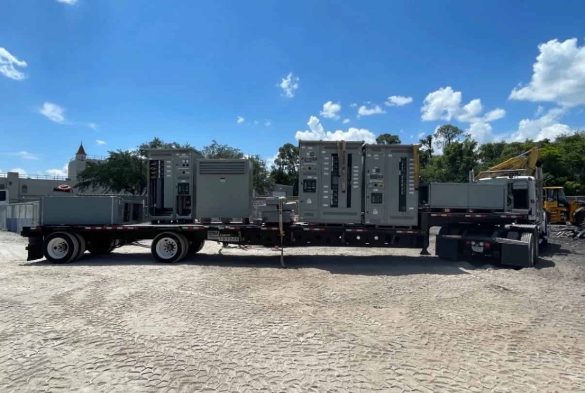
For a Lovelock project, delivery planning also deserves early attention. Confirm the shipping route, receiving access, unloading method, equipment-room entry dimensions, and the sequence for moving sections into place. Site conditions, construction progress, and available handling equipment can affect how assemblies are divided and delivered. These details should be coordinated before manufacture rather than assumed from a general shipping address.
Separate the EES branches and their distribution paths
NFPA 99 addresses health-care facility requirements, including electrical-system provisions, while NFPA 110 addresses emergency and standby power systems. Their applicability and the specific requirements for a project depend on facility classification, adopted codes, the authority having jurisdiction, and the approved design. The project’s qualified electrical engineer should determine the required essential-system arrangement; a switchgear supplier should build to the reviewed documents, not independently assign clinical loads to branches.
At a high level, the EES is commonly organized into life safety, critical, and equipment branches where required by the governing design. The documents should show which loads are served by each branch, where separation is maintained, and how distribution proceeds from the source and transfer equipment to downstream panels. Clarify whether branch distribution, feeder breakers, metering, or interface wiring is part of the switchgear scope. This prevents a branch name on a drawing from being mistaken for a complete, coordinated path to the served load.
Coordinate transfer sources and equipment interfaces
Source transfer is a system-level design decision. The engineer must coordinate normal and alternate sources, transfer equipment, generator capacity and controls, protective devices, and the loads intended to remain available. Transfer equipment may be included in a switchboard lineup or furnished separately, depending on the approved design and product configuration. Drawings should identify the equipment boundaries, control and status connections, interlocks, and responsibility for wiring and settings.
Whether transfer is open or closed transition, how loads are grouped, and where transfer occurs can affect equipment arrangement and coordination. These choices require engineering review and confirmation against the project’s applicable requirements; they should not be selected from a sales description alone. If separate transfer switches are specified, identify their manufacturer and interface requirements early. If they are part of a custom assembly, confirm the exact equipment scope and applicable product standards for that assembly.
Confirm ratings, construction, and feeder quantities
Provide the approved one-line diagram, panel schedules, load information, available fault-current data, and project specifications when requesting a quotation. The engineer’s documents should establish system voltage, phase and wire configuration, protective-device requirements, and the necessary equipment ratings. A rating is not the same thing as system voltage, and interrupting or withstand requirements must be checked against the actual system and design. Do not treat an unconfirmed rating or a general product description as proof of suitability.
For hospital projects, reconcile feeder quantities and destinations across the one-line diagram, schedules, and equipment layout. Identify spare or future provisions only where the design calls for them, and distinguish physical space from installed devices. Also confirm main and tie arrangements, incoming service details, metering, cable entry, and any required transition sections. UL 891 is relevant to applicable low-voltage switchboards; it should not be taken to cover every switchgear assembly or other voltage class. Listing status and standards for a proposed configuration require confirmation.
Plan delivery and room coordination in Lovelock
Before release, compare the lineup dimensions and shipping sections with the electrical-room plan, door and corridor clearances, floor and anchorage details, and cable-trench or conduit locations. Check where conductors enter and how field connections will be accessed. A compact room can create conflicts between lineup depth, working space, adjacent equipment, and the route for bringing sections indoors. The design team and contractor should resolve those constraints using project drawings and applicable requirements.
For shipment to Lovelock, establish who receives the equipment, what unloading resources are available, where it can be staged, and whether construction conditions allow direct placement or require temporary storage. Agree on the required feeder quantities, section identification, shipping splits, and delivery sequence early. These are planning inputs, not assumptions about local site capability or a promised delivery schedule.
Define commissioning responsibilities before startup
Commissioning should be planned among the owner, electrical engineer, installing contractor, equipment manufacturer, generator and transfer-equipment providers, and any commissioning authority. The project team should assign responsibility for submittal review, field connections, inspection, protective-device settings, functional testing, documentation, and resolution of deficiencies. Manufacturer checks of its equipment do not replace installation verification or system-level commissioning.
NFPA 110 requirements applicable to the emergency power supply system, and NFPA 99 requirements applicable to the health-care facility, should be interpreted and applied by qualified professionals using the adopted editions and project conditions. Test scope, acceptance criteria, and records should be established in the project documents. Before equipment is released for manufacture, resolve open questions about source-transfer interfaces, branch distribution, feeder counts, site access, and commissioning boundaries. Clear responsibility at these interfaces helps the hospital team coordinate the complete electrical system without relying on assumptions.