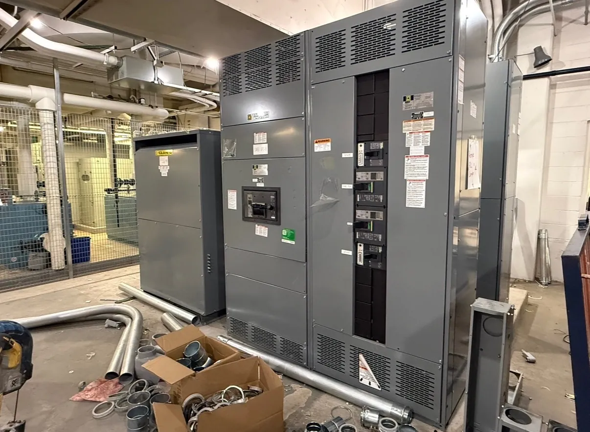
Medium-Voltage Switchgear for Lovelock, NV Projects
Medium-voltage switchgear is selected to control and protect distribution circuits at a defined system voltage. For a Lovelock project, the first step is to establish the equipment’s intended role: incoming service, feeder distribution, a transformer interface, or another function in the facility’s one-line diagram. The required configuration depends on the source and load arrangement, operating practices, available space, and the responsibilities assigned to the equipment. A quotation should be based on project documents and engineering review, not on a generic description of “medium voltage.”
Our U.S. manufacturing business builds new custom power-distribution equipment using all-American components. We manufacture equipment for customers and ship nationwide, including to Nevada. Project-specific scope, ratings, schedule, and delivery arrangements must be confirmed before an order is finalized.
Define Voltage Class, Fault Duty, and Insulation Level — Medium-Voltage Switchgear in Lovelock, NV
System voltage and equipment ratings are related but are not interchangeable. The project team should identify the nominal system voltage, grounding method, and applicable maximum operating conditions, then confirm the appropriate equipment voltage class. The available fault duty at the proposed installation point is another essential input. It must be established through the responsible engineer’s study and considered alongside protective-device characteristics and upstream system conditions.
Insulation level is a separate selection that must suit the equipment class and the project’s electrical requirements. Environmental exposure, altitude, and other site conditions may affect the engineering review or equipment configuration. A single voltage label does not establish that the fault rating, insulation level, or every component is suitable. Ratings and design details require confirmation against the current one-line diagram, utility or source information where applicable, and the project specifications. UL 891 applies to applicable low-voltage switchboards; it should not be used as a basis for describing medium-voltage switchgear.
Plan Feeder Quantities, Protection, and Relays
Feeder count influences the lineup arrangement, bus configuration, protection scheme, and available space for future changes. Provide the number and purpose of incoming, outgoing, tie, and transformer feeder positions, including any spare positions specifically required by the design. The engineer should also identify operating scenarios that affect interlocking or transfer functions rather than assuming these features from a general equipment description.
Protective relays must match the protection philosophy and coordinate with the system. Relevant inputs can include the functions required, instrument-transformer information, trip and control power, communication interfaces, and settings responsibilities. Relay selection alone does not establish a complete protection scheme: coordination studies, settings, and integration with upstream and downstream devices require qualified engineering. Clearly identify which party supplies, configures, reviews, and commissions each protection component.
Coordinate Cable Terminations and Physical Interfaces — Medium-Voltage Switchgear in Lovelock, NV
Incoming and outgoing cable arrangements should be settled early. Specify cable entry direction, conductor information, termination type, phase arrangement, and any project requirements for stress-control or shielding interfaces. Confirm that the proposed termination space and access suit the actual cables and installation method. These details can affect compartment layout and should be reviewed with the electrical engineer, cable contractor, and equipment manufacturer before drawings are released.
Also provide the intended lineup orientation, connection points, room or enclosure constraints, and interface requirements for grounding and control wiring. Clearances, access, and environmental protection depend on the installation and governing project requirements; they cannot be determined from the city name alone. Lovelock sites may have distinct building access, delivery routes, or handling constraints, so document those conditions without assuming a particular facility layout.
Prepare a Complete Lovelock Quotation Package
A useful request for quotation includes the current one-line diagram, equipment specification, system voltage and grounding details, available fault-duty information, required insulation level, and feeder schedule. Add relay and control requirements, cable termination data, site conditions, preferred lineup arrangement, and any required documentation or project interfaces. Identify deviations or unresolved items so they can be addressed before the design is treated as final.
Delivery planning deserves early attention. Confirm the destination, receiving hours, unloading equipment and responsibility, access limitations, staging area, and any restrictions on vehicle size or delivery sequencing. The customer and project team should clarify who receives the equipment and coordinates movement to its final location. These practical details can influence packaging and shipment planning, but a delivery date or handling method cannot be promised without project review.
Resolve Commissioning Responsibilities Before Release
Commissioning is a project activity, not an automatic consequence of purchasing switchgear. Define who is responsible for installation, inspection, field testing, relay settings, control-system integration, energization planning, and acceptance documentation. The equipment design, site wiring, protection studies, and commissioning scope should be reviewed by qualified engineers and the parties responsible for the installation. Agree on required submittals, drawing review milestones, and interface information while there is still time to resolve conflicts.
Our manufacturing team can develop a custom equipment scope from confirmed project requirements. Final ratings, listings where applicable, design details, and shipment arrangements depend on engineering review and the approved project documents. Early coordination among the Lovelock owner, engineer, installer, and equipment manufacturer helps align feeder needs, terminations, delivery handling, and commissioning expectations.