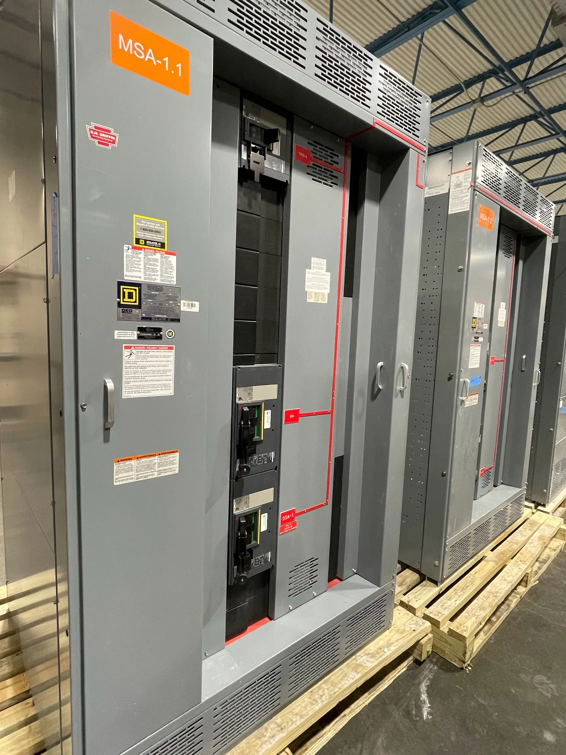
High-Voltage Switchgear for Lovelock Substation Projects
High-voltage switchgear is selected around the electrical system it must control—not simply the location where it will be installed. For a Lovelock-area substation project, the first engineering task is to establish the system voltage and the equipment’s required voltage class, then define the switching, isolation, grounding, and protection functions. Those terms are related but not interchangeable: a system’s nominal voltage does not, by itself, determine the equipment rating or insulation requirements. The utility, owner’s engineer, and equipment manufacturer need to confirm the applicable design basis before a construction can be specified or quoted.
We manufacture new custom power-distribution equipment in the United States, using all-American components, and ship nationwide, including to Nevada. The exact high-voltage construction available depends on the project requirements and must be confirmed during engineering. A project description alone cannot establish a suitable design, utility acceptance, or a delivery schedule.
Voltage Classification and Insulation Coordination — High-Voltage Switchgear in Lovelock, NV
Voltage classification should be documented alongside the system grounding arrangement, maximum operating conditions, and the insulation levels required by the project. Insulation coordination considers more than normal operating voltage: switching events, lightning exposure, grounding behavior, and the characteristics of connected equipment may affect the required withstand levels and protective devices. The engineer of record and utility determine the applicable criteria for the installation.
When requesting a quotation, provide the specified voltage class and insulation requirements rather than asking a supplier to infer them from a nominal system voltage. Identify any relevant altitude, ambient temperature, contamination, moisture, or other site conditions that could affect insulation or clearances. These conditions should be evaluated by qualified engineering personnel against the equipment’s proposed construction and applicable standards.
Switching Arrangement, Feeder Quantities, and Protection
Feeder count is only one part of the switchgear arrangement. The one-line diagram should show incoming sources, outgoing feeders, bus sections, tie points, transformers, and any bypass or transfer functions. The project team should state which circuits require switching, isolation, grounding provisions, metering, or protective relaying, and identify whether future expansion is expected. These choices influence the lineup arrangement, control interfaces, and space required for cable or bus connections.
Protection must be coordinated with the wider power system. Relay functions, instrument transformer requirements, trip and close circuits, control power, communications, and interface signals should be defined with the utility and project protection engineer. A switchgear quotation should not substitute for a fault study, coordination study, or site-specific engineering review. Final protective settings and operating logic depend on the complete system and the responsible engineers’ approval.
Utility Interconnection and Applicable Standards — High-Voltage Switchgear in Lovelock, NV
Interconnection requirements can affect the equipment’s electrical ratings, control scheme, metering, relaying, and documentation. Confirm the serving utility’s current requirements, the point of interconnection, ownership boundaries, required disconnecting or grounding functions, and review process before releasing a design. Utility requirements can vary by project, and the manufacturer should not assume that a design accepted elsewhere will be suitable for a Lovelock installation.
IEEE or IEC requirements may apply depending on the equipment type, project specification, and utility criteria. The applicable standard and edition should be identified by the project engineer. A standard reference is not, by itself, proof that a particular assembly is listed, certified, or approved for a specific installation. UL 891 applies to applicable low-voltage switchboards; it should not be treated as a general certification for high-voltage switchgear. Ratings, listings, standards compliance, and construction details require confirmation for the specific equipment being quoted.
Site Conditions, Delivery Handling, and Commissioning
Plan logistics alongside the electrical design. For a Lovelock site, confirm the delivery route, access restrictions, unloading equipment, laydown area, weather exposure, and any limits on shipment size or sequencing. Identify the receiving contact and who will inspect and protect the equipment after arrival. These details help establish practical packaging and delivery assumptions without presuming that a particular site has a specific road, crane, or storage arrangement.
Define commissioning responsibilities early among the owner, utility, electrical contractor, protection engineer, and equipment manufacturer. Clarify who handles installation checks, cable and control connections, relay configuration, testing, utility witness requirements, and authorization to energize. The scope and sequence must be agreed for the project; no commissioning or energization decision should be made without qualified personnel and site review.
Information to Prepare for a Project Quote — High-Voltage Switchgear in Lovelock, NV
A useful inquiry includes the one-line diagram, voltage classification, insulation requirements, feeder quantities, fault-duty and grounding information, protection and control requirements, applicable IEEE or IEC specifications, utility interconnection criteria, and site environmental conditions. Include preferred delivery sequence, access and unloading constraints, and the planned division of commissioning work. If any item remains undecided, identify it as pending rather than assuming a value. Early coordination lets the project team resolve design dependencies before equipment details and delivery plans are finalized.