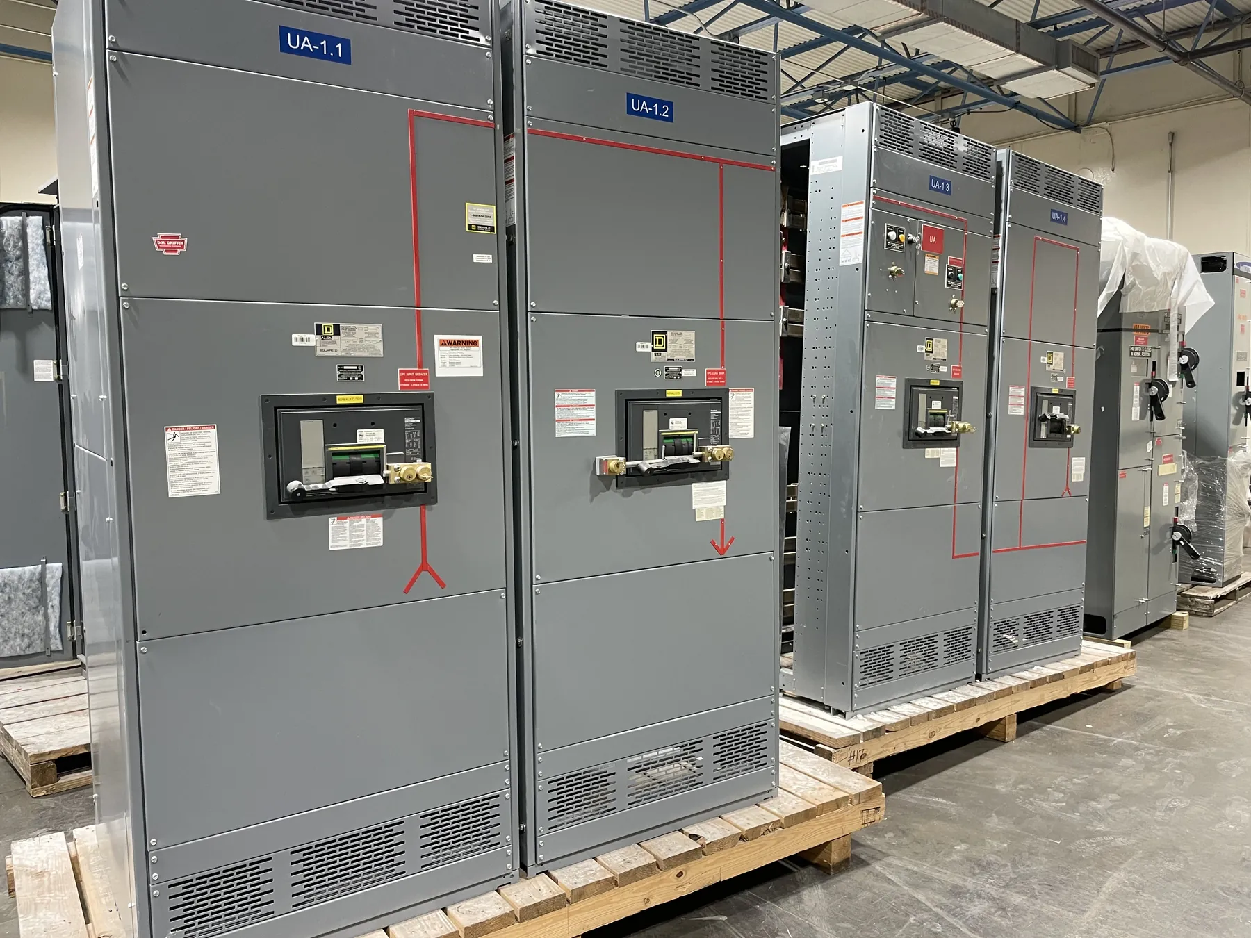
Utility Switchgear for Lovelock Service Requirements
Utility distribution work in Lovelock starts with the service boundary, not a generic equipment schedule. The serving utility’s requirements, the project’s load and the owner’s operating needs determine what switchgear must do and how it interfaces with the incoming service. A custom assembly can be configured around those documented requirements, but utility acceptance is not implied by a product description or by the equipment’s ratings. Confirm the applicable service standards, review process and approval responsibilities with the utility and project engineer before design is finalized.
Establish which party furnishes, owns and maintains each part of the installation. The point of delivery, ownership demarcation and location of revenue metering affect compartment layout, access, wiring interfaces and responsibility for commissioning. Utility requirements may specify equipment arrangement, seals, instrument-transformer provisions, test access or separation between utility and customer spaces. These details should be resolved in writing; a change to metering location or service configuration can alter the enclosure and the construction documents.
Interconnection, Metering and Protection Interfaces
Interconnection design must account for the source, service configuration and the utility’s stated protection criteria. Provide the design team with available service data and the utility’s requirements for protective devices, control power, trip interfaces, relaying and communications, where applicable. The engineer can then determine how the switchgear coordinates with upstream protection and downstream equipment. Do not assume a breaker frame, trip setting or relay function from a nominal system voltage alone. The selected equipment rating and settings depend on the project study, available fault information and the intended operating arrangement.
Metering provisions are similarly project-specific. Confirm whether metering is utility-furnished or customer-furnished, which instrument transformers and terminal arrangements are required, and who supplies wiring, cabinets and communications interfaces. Clearly document access and compartment boundaries so utility personnel can review the arrangement without creating conflicts with customer maintenance or operations. Final metering details remain subject to the utility’s review.
Feeder Quantities, Grounding and Ratings
Feeder count and function are essential quotation inputs. Identify the incoming source, each outgoing feeder, expected load, protective-device requirements, spare provisions and any future expansion that is part of the current scope. A spare breaker position is not automatically equivalent to a fully equipped future feeder; define whether future provisions include bus connections, terminals, controls or other components. More feeders can affect lineup length, cable space, heat management and access, so a preliminary one-line diagram and feeder schedule help avoid late layout changes.
Grounding and bonding must follow the engineered system arrangement and applicable project requirements. Specify the grounding method, neutral treatment where relevant, grounding connections and any interface to site grounding conductors for review by the qualified electrical engineer. Likewise, distinguish system voltage from equipment voltage and current ratings. Ratings, short-circuit withstand, interrupting capability, enclosure details and any requested listing must be verified for the exact assembly and application. UL 891 applies to applicable low-voltage switchboards; it should not be taken as a blanket standard for every switchgear product or voltage class.
Custom Manufacturing and Documentation
We manufacture new custom power-distribution equipment in the United States using all-American components, and can build an assembly to the approved project requirements. A useful request for quotation includes the one-line diagram, service and utility criteria, equipment schedule, feeder list, required ratings, metering and protection interfaces, enclosure conditions, cable entry preferences and requested documentation. Include drawings or specifications for adjacent equipment when they define bus, control, conduit or communication connections. State which party will provide engineering studies, final settings, utility submittals and field connections.
During submittal review, compare the proposed lineup with the latest utility comments and project documents, rather than relying on an earlier concept drawing. Confirm dimensions, shipping sections, access clearances and connection locations with the site team. Any requested listing, label or standard should be identified for the specific equipment type and confirmed during quotation and engineering review; it should not be assumed from another product in the lineup.
Lovelock Delivery and Site Coordination
For a Lovelock project, delivery planning should be coordinated with the facility’s actual receiving conditions. Confirm the delivery address and contact, unloading equipment and responsibility, access route, gate or site restrictions, staging area, weather exposure and the path from unloading point to final location. Lineup dimensions and shipping splits need to suit both transport handling and installation access. Provide those constraints early, especially if the equipment must pass through an existing building or arrive when site access is limited.
We support short lead times and ship nationwide, but timing depends on the approved scope, engineering completion, component requirements and production scheduling. A requested delivery window is not a confirmed ship date until the project details and schedule have been reviewed. Identify the required feeder quantities and any phased delivery expectations at the outset so the quotation can address the intended configuration and logistics.
Commissioning Responsibilities and Acceptance
Agree early on who coordinates utility inspections, equipment installation, field terminations, testing, protection settings and commissioning records. The manufacturer’s supplied scope, the electrical contractor’s work, the engineer’s verification and the utility’s acceptance are distinct responsibilities. Document required submittals, inspection points and turnover materials, and allow time for utility review and site-specific commissioning planning. Qualified electrical professionals must confirm the design, ratings, installation and acceptance criteria for the actual service. Clear responsibility assignments help keep Lovelock utility work aligned from quotation through energization without treating equipment delivery as a substitute for project approval.